| www.ethanwiner.com - since 1997 |
The Oscilloscope
by Ethan Winer
This article first appeared in the August 1982 issue of Recording-engineer/producer magazine.
Of all the test instruments available to audio engineers, the one
most frequently taken for granted - yet often least understood - is probably the
oscilloscope. Anyone can figure out how to use a voltmeter, and an oscillator and
frequency counter are more obvious still. There are many recording engineers, however, who
wouldn't recognize slew rate limiting if it were staring them in the face. This article
will attempt to demystify the most versatile of all audio tools.
BASIC PRINCIPLES
The main purpose of an oscilloscope is to display the level of a signal relative to changes in time. A voltmeter is fine for measuring steady levels like test tones or for checking flashlight batteries, but it is impossible to observe a signal's instantaneous value - or to determine whether you have a square wave or a sine for that matter - since the meter's pointer could never move that fast. An oscilloscope uses an electron beam which creates a dot of light when the beam strikes the phosphor coating inside a cathode ray tube (CRT). The beam is then swept across the screen quickly enough to follow variations in the input waveform.
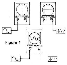
Besides the CRT, all scopes also have both vertical and horizontal
amplifiers, as well as a variable frequency sawtooth oscillator connected to the latter.
The purpose of this oscillator is to create the recurrent sweep that makes tracing the
input signal possible. Since the CRT produces a single dot of light, the dot must be swept
constantly from left to right to create the illusion of a continuous solid line. The
signal to be observed is then applied to the vertical amplifier's input which shifts the
dot up or down, as shown in Figure 1.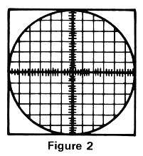
Without the horizontal sweep there would only be a single dot in the center of the screen; applying a signal into just the vertical input simply moves the dot up and down. By using both the vertical and horizontal inputs the signal's voltage can be determined by the amount of vertical deflection, and its frequency by the horizontal position. Both can be read directly from the calibrated lines, called a graticule, that is drawn on the face of the CRT (Figure 2).
Switches set the gain of the vertical amplifier which is calibrated in volts per division. The frequency of the horizontal sweep oscillator is controlled in a similar fashion, and determines how long it takes the dot to move one division to the right. When the dot reaches the right edge of the screen the sawtooth ramp quickly resets, and in all but the least expensive models the dot is turned off during this time. Otherwise a confusing double trace would result, especially at the higher sweep speeds. Okay, that's the basic concept. Now let's look at some of the refinements you'll find in a commercial oscilloscope.
ADDITIONAL FEATURES
The most important feature is a triggered sweep, which serves to synchronize the sweep oscillator to the input waveform. Without this feature the displayed waveform would constantly flicker and wander about, since each time the sweep began the input would likely be at a different part of its cycle. Instead of immediately beginning a new sweep as soon as the beam is reset, the trigger circuit delays the sweep until the input signal returns to the same voltage as when the last sweep began. Triggering usually occurs on the rising edge of the input waveform, though better scopes have a switch that lets you trigger on either the rising or falling edge.
Another standard feature is a continuously variable level control on the vertical input for making relative, rather than absolute, voltage measurements. If you are measuring the response of a filter, for example, you would use this control to make the unfiltered wave exactly fill the screen. Then, it is easy to see when the signal becomes attenuated by a half, a quarter, or whatever after passing through the filter. In fact, many scopes have an additional dB. scale printed on the screen to allow these readings directly. Likewise, a calibrated fine-tuner called a vernier is provided for the horizontal sweep speed as well, to simplify relative frequency measurements. Also, every oscilloscope has an AC/DC switch - just like a voltmeter - to observe only the AC voltage regardless of any DC offset present in the signal. This is useful for inspecting small levels of high-frequency noise on a power supply's output, and it lets you raise the vertical gain without the trace going off the top or bottom edge of the screen.
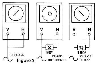 Most scopes let you
disable the automatic sweep, and most also let you feed a signal directly into the
horizontal amplifier to measure the phase difference between two inputs. Used in the X/Y
mode like this, it is simple to optimize the azimuth alignment of a recorder's tape head
by comparing the relative phase between two tracks. As shown in Figure 3, when two
identical (in-phase) signal sources are applied to each input a diagonal line results.
Contrast that to the other patterns you get when different amounts of phase shift are
introduced. Thus, to adjust a tape head's azimuth you feed the output from an upper track
to the Vertical input and a lower track's output to the horizontal input, then adjust the
head angle until the line goes from the lower left to the upper right of the display. This
method is considered by many to be more accurate than simply maximizing output level while
looking at the recorder's VU meters.
Most scopes let you
disable the automatic sweep, and most also let you feed a signal directly into the
horizontal amplifier to measure the phase difference between two inputs. Used in the X/Y
mode like this, it is simple to optimize the azimuth alignment of a recorder's tape head
by comparing the relative phase between two tracks. As shown in Figure 3, when two
identical (in-phase) signal sources are applied to each input a diagonal line results.
Contrast that to the other patterns you get when different amounts of phase shift are
introduced. Thus, to adjust a tape head's azimuth you feed the output from an upper track
to the Vertical input and a lower track's output to the horizontal input, then adjust the
head angle until the line goes from the lower left to the upper right of the display. This
method is considered by many to be more accurate than simply maximizing output level while
looking at the recorder's VU meters.
Another useful feature found on medium- and high-priced scopes is
dual-channel capability, which is essential if you want to be able to view two different
signals simultaneously. These oscilloscopes let you switch between two different
two-channel modes: Alternate and Chop. In the Alternate mode, a sweep is performed first
on one signal in the top half of the CRT screen, and then on the other signal in the lower
half of the display. The Chop mode is created by a single sweep, with the channels
switching back and forth very rapidly. For a readable display (to avoid phantom alias
frequencies), the chopping frequency must be much higher than that of either input
frequency. Some oscilloscope models have four or eight inputs - the ultimate in digital
circuit monitoring - and adapters are also available for regular scopes to let them
display many different inputs at once.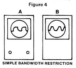
A built-in square wave generator is another common accessory, and it is used to calibrate the scope's Volts/division vertical trimmers, as well as provide a high-quality source for "rise-time" testing. Which brings us back to recognizing slew-rate limiting. First, all audio equipment has a limit to the highest frequency it will pass. When viewing a square wave this limitation results in a rounding of the wave edges as shown in Figure 4A. If the rounding doesn't occur until 50 KHz. or so there is no problem - unless you believe you can hear that high. But real problems do occur when an amplifier stage cannot supply the current required to charge up the various circuit capacitances. Then the signal begins to look like Figure 4B, where the straight triangle lines reveal distortion as well as bandwidth restriction. If you aren't concerned about being able to pass a Megahertz signal, a simple Resistor/Capacitor filter can be added to an amplifier's input to prevent extremely high frequencies from getting in to begin with.
Once you get to the most expensive oscilloscope models you'll find storage capability, which is a method to freeze the display even after the input has been removed. Early storage scopes used a charged grid inside the CRT face to retain the beam pattern, though current units use digital memory that is looped much like the repeat-hold feature of a digital delay line.
Entire contents of this web site Copyright © 1997- by Ethan Winer. All rights reserved.