 |
| www.ethanwiner.com - since 1997 |
The Audio Circuits Cookbook
When an op-amp is set for a large amount of gain, its DC input offset voltage is also amplified along with the audio. So an op-amp whose input offset voltage is only 5 mV will output half a volt of DC when set for 40 dB of gain. This creates a nasty pop sound when you connect the circuit's output to an amplifier. One common solution is to add an electrolytic capacitor in series with the gain resistor between the op-amp's minus input and ground, shown as C1 in Figure 6.9 in the book. But as explained in the accompanying text, it's not obvious which way to place a polarized capacitor. Another solution is to add a series output capacitor. The op-amp's output might have as much as 1 volt DC, which is probably okay when running from +/- 15 volt supplies. But then that cap has the same problem if it needs to be large enough to drive a low impedance input. For example, to drive a 600 ohm load requires an 18 uF capacitor in order to be -3 dB at 15 Hz.
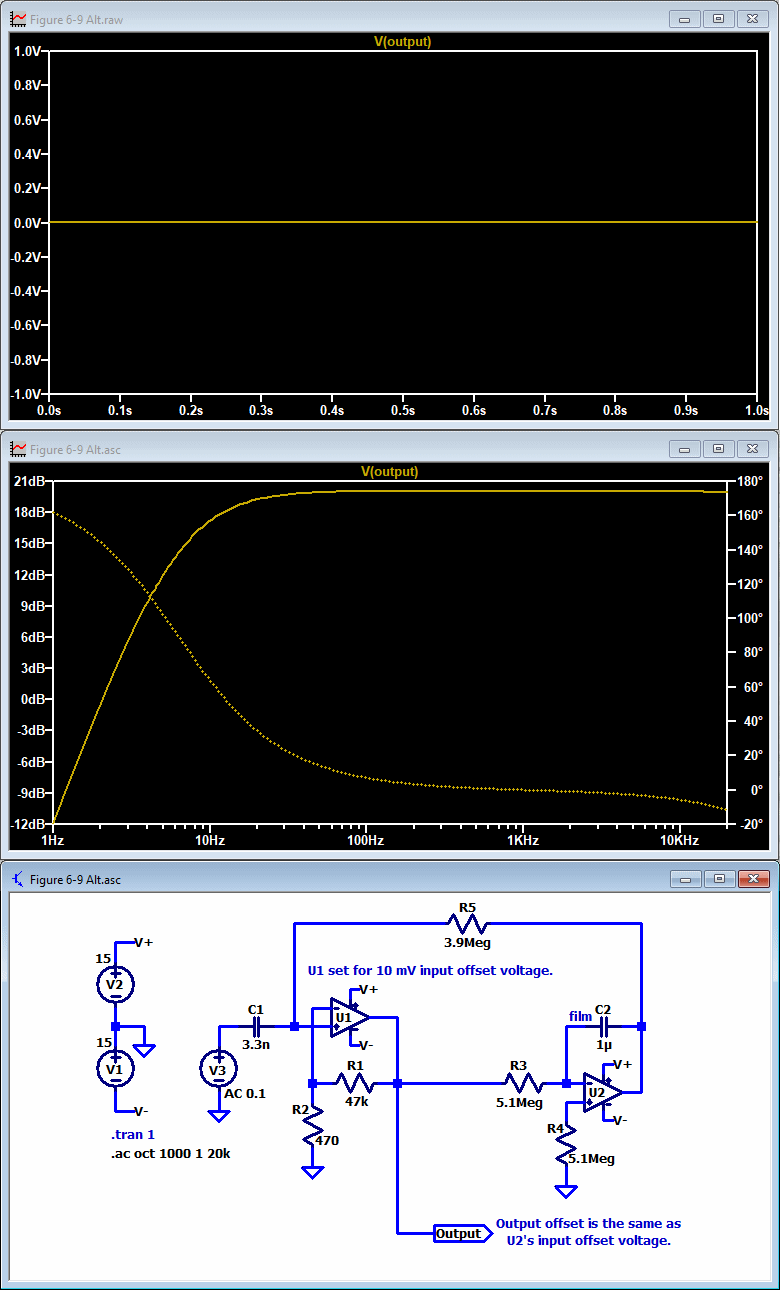
When I asked my expert friend Bill Eppler for a solution, he shared a clever circuit that avoids amplifying an op-amp's input offset voltage. This requires a second op-amp, but that will probably cost less than a large electrolytic cap, especially if you already have an extra op-amp in a dual or quad package. The circuit below, adapted from the upper circuit in Figure 6.9, replaces the blocking capacitor with an integrator that provides negative DC feedback. This feedback sets the main op-amp's DC output to the input voltage offset of the integrator's op-amp regardless of its gain. The upper display shows the DC output offset, with the frequency response below.
 |
The response above shows a level of +20 dB because the input voltage is 10 mV and 40 dB of gain raises that to +20. The low end is -3 dB at 10 Hz based on the values of both C1 and C2. The output impedance of the driving device (V3, or a passive guitar pickup) doesn't change the response or offset, though the values for C1, C2, and R3 through R5 should not be changed. Note that the lower circuit in Figure 6.9 of the book doesn't need this solution because it runs on a single supply, so the polarity of its electrolytic capacitors is clearly evident.
You can download the LTspice file for this circuit HERE in a Zip file. To switch from the frequency response display to waveform oscilloscope view, right-click the .tran command then select OK.
Entire contents of this web site Copyright © 1997- by Ethan Winer. All rights reserved.