| www.ethanwiner.com - since 1997 |
Build A Stereo Synthesizer
by Ethan Winer
This article first appeared in the June 1979 issue of Recording-engineer/producer magazine.
There are many ways to create a stereo effect. If you were miking a
piano, a string section, or some other large sound source, you'd probably stick up a pair
of directional mikes and assign them left and right. But what if you want to
"enlarge" a lead vocalist? Or, how about other inherently mono instruments like
an electric guitar or a synthesizer? Well, you could delay one side or use a Harmonizer or
some other related gadgetry, but generally with this method the stronger the effect you
create, the more you'll jeopardize mono compatibility. A short delay will cause phase
cancellations in mono, while longer delays can create a disturbing slap echo. (I
personally know some rock bands that would consider this to be a plus, though you'd never
get away with it on a jazz purist or - gasp - an opera singer.) But seriously, an even
better approach might be to simply EQ the two sides differently. Unfortunately, for a
soloist desired up front and centered, the brighter sounding side will dominate. So what's
really needed is a better method for changing the equalization - more than just adding top
or bottom.
One method is to employ several transition or crossover points in the frequency response between the two channels. In other words, the low bass range will come out of one speaker, and the high bass from the other. The low mid-range comes from the first speaker, and so on. We must be sure, though, that the sum of the two channels always equals the original mono source if compatibility is to be maintained. You don't process the entire mix, of course; only the tracks that you want to enhance.
The black box wonder about to be described fulfills these basic criteria and more. The frequency crossover points can be varied either manually or automatically with a built-in, variable low frequency oscillator. The manual adjustment is useful for finding the best crossover points for a given instrument or track. The automatic sweep provides a good rotating speaker sound while the stereo output further heightens the effect. If you use only one of the outputs, you will have a phase shifter similar to many currently on the market. This is not a true time delay type phaser [these days called a flanger], but then neither are many of the others. Incidentally, when you're using this for a phasing effect, try each output separately because the sweep ranges are different for the two channels and obviously the sound will be, too.
HOW IT WORKS
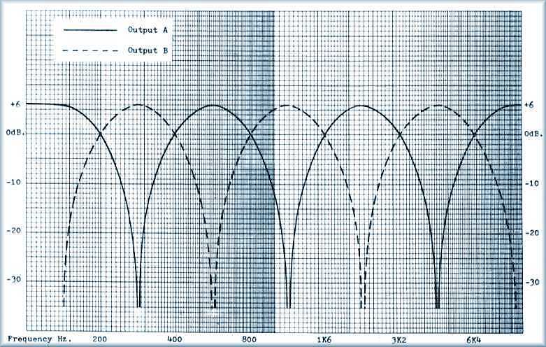
As mentioned earlier, different frequency ranges appear at the two outputs, depending on the setting of the controls. To be a little more specific, the actual crossover points are as follows (it helps to look at the graph): Frequencies below 200 Hz. are at output A, while the high bass from 200 Hz. to 400 Hz. is available at output B. We go back to output A for the mid-range from 400 Hz. to 800 Hz., while the octave from 800 Hz. to 1.6 KHz. is at output B again. The crossovers continue on at octave intervals comprising a total of six transitions spread over a five octave range. Again, this entire set of dips and peaks is sweepable over a ten-to-one range. The lower limit occurs at 30 Hz., and the highest is at 9 KHz. The depth of the notches is also continuously adjustable from zero (no effect) to a maximum of near infinity. If you were to use 1% resistors in the final combining stage, you could get even closer to perfect notches, but a depth of 40 or 50 dB. is really more than sufficient. The automatic oscillator rate is adjustable from about 4 or 5 seconds per sweep at the slowest, to 10 Hz. or so which is probably faster than you'll ever need.
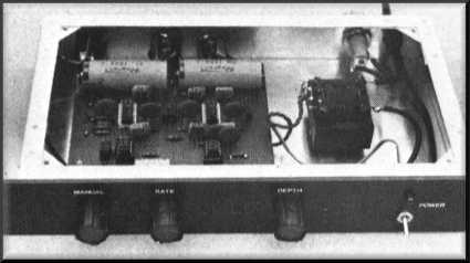
On the prototype I used a switch attached to the rate control to select between manual and auto-sweep. Like a radio where you shut off the power by turning past minimum volume, turning counter-clockwise past "slow" will disconnect the oscillator and engage the manual control. This potentiometer/switch combination is available at any radio supply store, as is the 10 uF. non-polar capacitor. Naturally, you can use a separate switch if you want to. While I'm on the subject of parts, just about any junction type FET will work in this circuit. The FETs should all be the same type, of course, though matching is not necessary. Simply adjust the 10K trimpot in the oscillator circuit for the smoothest sounding sweep. This is the only setup adjustment required and can be easily accomplished without any test instruments.
HOW IT REALLY WORKS
The signal at the input is first sent to a low noise IC op-amp configured for a loss of about 10 dB. This loss is needed to reduce the signal voltage present across the FETs, which minimizes harmonic and IM distortion. Local feedback around each FET helps to reduce distortion even more. The input op-amp also serves as a buffer to insure proper circuit operation regardless of the output impedance of the preceding equipment. Next, the signal is split into three different branches for further processing. One path leads to a phase shift section that is made up of six smaller stages connected in series. The amount of phase shift for a given frequency is adjustable by varying the DC voltage applied to the FET gates. It is this voltage controlled capability that makes the auto-sweep feature possible. The remaining branches are then combined with the output of this section, though in opposite polarities. (Follow the plus and minus markings on the op-amps.) This yields notches and peaks in the response that are different for the two outputs.
The low frequency oscillator provides a triangle waveform of
slightly less than 1 volt when measured from peak-to-peak. The rate control varies the
amount of current available to charge the 10 uF. capacitor thereby controlling the
frequency sweep rate. The 10k trimpot is then used to center the waveform within a useable
range for the particular FET being used. This range does vary from type to type and even
for different brands of the same type. One important note: If you are using P-channel
FETs, be sure to connect the 120K resistor on the manual sweep control to the V+ supply
instead of V-. Nothing will be damaged if you don't, but then it won't work very well
either. (See the parts list for some recommended FET substitutions. This may save you
trouble if you can't locate the 2N5457s used in the prototype.)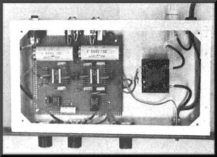
CONSTRUCTION
There are a few routes you can take in constructing the stereo synthesizer - using either perf-board or a printed circuit. The former probably makes more sense though, as you'll only be making one. And besides, in the time spent just designing the PC layout pattern alone, you could have built the darn thing. Circuit boards are great, but only when you're making many of something. The only perf-board really usable with ICs is the kind that has holes in rows one-tenth inch apart. This will line up with the standard lead spacing for all ICs and IC sockets as well as any other components you'll be using. By the way, if you decide to use IC sockets, never use a gold plated socket if the ICs have tin plated leads or vice versa. Many people don't realize this, but over the years, corrosion can result from the dissimilar metals if even the tiniest impurities (like sweat or other moisture) gets on the mating surfaces.
For most audio work, carbon film resistors are generally preferred rather than standard carbon composition. The film types have lower self-generated noise levels, suffer much less from temperature drift, and usually have a tighter initial tolerance. Interestingly, the film types also cost less.
A sturdy aluminum box is your best bet for an overall enclosure. If you like, you can rack mount the unit by using a standard panel with holes drilled for the controls and power switch. The holes then align with those in the chassis and the controls go through both pieces. When all of the nuts have been tightened, the assembly will be secure.
TAKE IT AND USE IT
As the effects of the stereo synthesizer can range from very subtle to the bizarre, care should be taken when approaching certain types of music. You would not, for example, process a delicate flute solo with a rapid sweep at full depth, as the constant image shift will provoke the flautist to do you bodily harm. The sweep is very pleasant, however, on certain other instruments. The electric bass takes on a new, electronic dimension and once you hear it on a Rhodes, you'll never mix down without it. When the sweep is off and the image stays fixed, the effect stops drawing attention to itself - even at full depth. Though you might think that the comb filter effects would be obvious and therefore objectionable to many people, it is not so noticeable, even when standing nearer to one speaker. The brain apparently fuses it all back together and even with earphones it doesn't sound "phased," as long as the channels are reasonably well balanced.
Stereo Synthesizer Specifications
Residual noise: -89 dBm. "A" weighted at maximum output of +18 dBm.
Frequency response: +/- 1 dB. 20 Hz. - 20 KHz. with depth at minimum or composite mono
Distortion measured at 0 dBm. input and output): 0.03% THD, 20 Hz - 20 KHz.; 0.012% IMD, 7 KHz./60 Hz. mixed 4:1 (SMPTE)
Note: Because of the inherent nature of this device (that is, notches and peaks), it is difficult to judge THD and IM distortion. These specs are mostly governed by the op-amps used, but at certain control settings may degrade to 1% or more.
Parts List
Quantity |
Item |
2 |
150 ohm resistor |
1 |
330 ohm resistor |
7 |
1K resistor |
19 |
10K resistor |
3 |
33K resistor |
5 |
47K resistor |
13 |
100K resistor |
4 |
150K resistor |
1 |
1.5K resistor 1/2-watt 5% |
1 |
10K PC-mount trimpot |
2 |
10K potentiometer, linear taper |
1 |
10K potentiometer, log taper with DPDT switch, Radio Shack No. 271-215 |
3 |
15 pF. capacitor, disc or mica |
1 |
30 pF. capacitor, disc or mica |
18 |
0.1 uF. capacitor, disc |
1 |
10 uF. capacitor non-polarized electrolytic, Radio Shack No. 272-999 |
2 |
1000 uF. electrolytic, 25 volts |
2 |
TL074 quad FET op-amps (Texas Instruments) |
1 |
NE5534 10-noise op-amp (Signetics) |
1 |
1458 dual op-amp |
6 |
2N5457 field effect transistors |
1 |
power transformer 20 to 24 volts AC center tapped |
1 |
bridge rectifier assembly, 1 amp/50 v |
1 |
power switch |
1 |
1/8 amp slow blow fuse in suitable holder |
1 |
LED indicator |
1 |
aluminum chassis, 1-3/4" rack mount panel optional |
Note: If you can't find the 2N5457 transistors you can substitute 2N5458, or 2N4091-2-3, or 2N4391-2-3, or any general purpose FET designed for use as a variable resistor amplifier.
Click here to view the complete schematic (230k GIF file).
Entire contents of this web site Copyright © 1997- by Ethan Winer. All rights reserved.