| www.ethanwiner.com - since 1997 |

The Hardware Tutor
By Ethan Winer
Drawings by Jay Munro
Welcome to The Hardware Tutor - the BASIC programmer's guide to understanding hardware and electronic circuits. In this tutorial I will cover many of the principles and concepts that go into the physical design of audio and digital circuits, as well as a number of related topics. All of the subjects will be explained in the clearest language possible, and the use of jargon will be avoided. The important thing to remember is that there is nothing inherently difficult about understanding electronics, and all that's really required is a genuine desire to learn. If you can program a computer, then you've obviously got the right kind of aptitude.
When this tutorial was first conceived, I had a clear idea as to how the topics should be presented. No mathematics would ever be used in any of the discussions, and technical words that contained more than three syllables were to be avoided. It is my sincere belief that nearly any electronic concept can be explained in practical, perhaps mechanical terms to those who may be technically uneducated, but are none the less seriously interested.
Not unlike programming, electronics is a broad subject that encompasses a wide range of topics. For example, there is audio, radio, television, microwave, and of course digital. And within these disciplines are a number of other, even more specialized areas. In this discussion we won't get involved with esoteric subjects, though we will certainly go beyond simple analog, digital, and computer circuits.
It is amazing how often technical terms get tossed around in the popular press, but with no meaningful explanation. For example, how many programmers really understand the operation of a switching power supply? Or a 120 nanosecond RAM chip? Even the distinction between parallel and serial ports eludes many who are otherwise quite knowledgeable about their PCs. In truth, none of these concepts are difficult to grasp, once they have been clearly explained.
 Obviously,
a thorough understanding of electronics is not essential to being a good programmer,
though it can occasionally be useful with assembly language. For example, you may need to
write a routine to position a floppy drive head, or control video synchronizing on a
display card. But aside from the practical considerations such as repairing or modifying
your PC, electronics can also be fun - even if you're not the technical type.
I know many programmers who are quite interested in the inner workings of their equipment, but get discouraged by all the math and physics they believe must be learned before a true appreciation is possible. After all, electronics is somewhat less obvious than, say, mechanical engineering, where you can readily observe the action of the various gears, pulleys, and levers. Similarly, it's not easy to envision electricity in a wire, compared with the flow of water through a pipe, or the action of a faucet where you can see, feel, and hear the mechanisms at work.
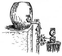 I
want to assure you that electricity and electronic components adhere to the exact same
laws of physics as their mechanical counterparts. For example, just as it is hard to move
a lot of water through a very small pipe, it is equally difficult to move much electricity
through a thin gauge of wire. And to carry the analogy even further, voltage can be
likened to the amount of water pressure, while current is similar to the number of gallons
per minute flowing through the pipe.
When you turn off a bathroom faucet, the pressure is still there in the pipes. Likewise, when you unplug a lamp from the outlet on the wall, the voltage is still present at the socket, even if it isn't being consumed. But before we go off into the world of volts and amps, let's first consider some more fundamental concepts.
ANALOG VS. DIGITAL
Most electronics enthusiasts generally fall into one of two camps: digital or analog. As you must already know, digital circuits are comprised of voltages that are either On or Off, which in computerese is referred to as One and Zero. A good example here would be your emergency flashlight - it's either turned on or it isn't.
Analog circuits, on the other hand, can contain a range of possible values, for example the voltages traveling through an audio amplifier that powers a loudspeaker. On soft passages of music, the voltage produced is very small and the speaker moves back and forth only slightly. But when the music becomes louder, the voltage and movement will be that much greater. With audio, though, how quickly the speaker moves is also a factor.
ELECTRICITY FUNDAMENTALS
To begin at the very beginning, all electric circuits require two wires to operate. Unlike water that simply flows from here to there, electricity requires a return path back to the original source. This is why a battery has two terminals and a 115 volt floor lamp has two wires. If you interrupt either wire the flow of electricity will stop, which is of course the basis for a switch, the most primitive of all components.

RESISTORS
Lots of times, an on/off switch is sufficient, but what if you'd like to be able to vary the brightness? This is where resistors come in. A resistor is a component that is meant to be inserted into an electrical path, to restrict the flow of electricity. To continue the water analogy, a resistor is very much like a short length of narrow pipe. Most resistors come with two connecting wires, one at each end, so they can be added to the circuit. There are also variable resistors such as the volume control on a portable radio, and they operate much like a water valve or faucet.
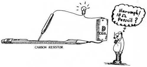
The value of a resistor is measured in Ohms, and the higher this value is, the less current will be able to flow through it. When a resistor is inserted into either of the wires that connect a battery to a light bulb, less current is passed and the bulb will be dimmer. By the way, most of the resistors that you will encounter are constructed of some type of carbon material. In high power circuits, thin wire is generally used instead, which is then wound on a ceramic core that won't melt.

CAPACITORS
Capacitors are slightly more difficult to understand than resistors because there is no physical connection through them, though some types of current can still get through. But how can this be if there is no metal or other conductor? Before answering this question, let's first digress for a moment and consider the difference between alternating current (AC) and direct current (DC).
Direct current is the type of electricity you'd think of when using the water comparisons. That is, the current flows in only one direction. But with an alternating current, the direction is instead constantly changing. For the electrical circuits in your home, the direction alternates exactly sixty times per second. With audio (or radio) circuits, the range of frequencies is much greater.
Now let's see if we can find a suitable mechanical equivalent for a capacitor. How about a leaky bicycle pump? The type of pump I'm referring to consists of a plunger that is placed within a hollow metal tube. Now imagine that the plunger is not very well sealed, perhaps because it's a bit undersized. If you push the plunger very slowly, almost all of the air will leak back out. But if you increase the frequency of the pumping, less air will escape compared to the amount that travels the intended path. And if you give the pump a single fast push, some pressure will be developed though in a few moments it will dissipate.
In a similar manner, a capacitor allows electricity to flow, but only so long as the voltage is changing. Though there's no physical connection through it, a light bulb attached to a battery through a capacitor will flash briefly when they are first connected together.
The whole point of capacitors, therefore, is that alternating
currents can pass through them, while direct currents cannot. Further, the higher the
frequency or rate of change, the more current will be able to get through. It's not hard
to see how capacitors are valuable in the design of the treble and bass controls on your
stereo receiver.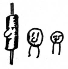
Internally, a capacitor consists of two pieces of metal in close proximity, but not quite touching. If you can picture a piece of plastic food wrap sandwiched between two strips of aluminum foil, you're getting the general idea. A wire is attached to each strip of foil, and the whole thing is rolled up to save space and then dunked into goo that hardens. If you haven't done this, I recommend buying an assortment of resistors, capacitors, and other components at Radio Shack, just to bust them open and see what's inside. This is not only quite educational, but a lot of fun as well.
Besides allowing a circuit to pass only higher frequencies, capacitors are also useful for their storage capability. In fact, a capacitor is not unlike a rechargeable battery, since it can also hold a charge. But that's another issue we will discuss later. By the way, the larger a capacitor's metal surfaces are, or the closer they are together, the higher its capacitance will be.
The value of a capacitor is measured in Farads, though you'll
probably never see one that large. Similarly, you won't find a one Ohm resistor very often
either. When Messrs. Ohm and Faraday discovered these properties long ago, they really had
no concept of the way their components would be used today.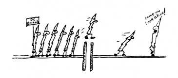
Typically, capacitors are measured in microfarads, and just as often, picofarads (millionths and trillionths of a Farad respectively). Resistors of ten or one hundred Ohms are not that uncommon, but most of the ones in your PC are measured in Kilohms (1000 Ohms).
INDUCTORS
The complement to a capacitor is an inductor, which is merely a coil of wire, frequently wound on an iron core. DC has no trouble passing through an inductor since it is, after all, made of wire. But alternating currents have an increasingly difficult time, and as the frequency is raised less and less current will appear at the other end.
Inductors are measured in Henries, though again, most of the ones you're likely to encounter will be rated in millihenries or even microhenries. As more and more wire is added to the coil, the larger its value will be, and the less able high frequencies are to get through it. The amount of iron used for the core also has an effect, with more iron increasing the inductance.
In practice, inductors are not always used where they could be, since they may be simulated less expensively using other components. (A complex issue not worth getting into here.) Copper wire and iron are quite expensive these days, plus an inductor's bulk and weight don't lend themselves to today's miniaturized equipment. However, the real point is that an inductor is also frequency sensitive, and it is exactly the opposite of a capacitor.
BUT DON'T BLOW IT UP!
Before continuing on to diodes, transistors, and the other
solid-state components, there is one other item we should consider. As we've already seen,
resistors are measured in Ohms, capacitors in Farads, and inductors in Henries. But each
of these has another rating too, which relates to how much electricity they can handle
before blowing up or melting.
If you've ever watched a Frankenstein movie, you must realize that whenever a voltage gets beyond a certain level, it will jump through the air to get to the other contact. In fact, this is precisely what makes lightning jump from the sky to the earth. The same thing happens with a capacitor when its voltage rating is exceeded. Of course this will be on a much smaller scale, but the effect is the same.
Though some type of insulation is placed between the metal plates of every capacitor, if too much voltage is applied the insulation will become punctured rendering it useless. Therefore, besides the usual measure of its capacitance, all capacitors have a maximum voltage rating as well.
Resistors and inductors can also be damaged, though in this case by applying too much current. Just as trying to force too much water through a pipe will cause it to rupture, the same thing can happen to a resistor or inductor. There are formulas that tell how much current and voltage is allowable for any given circuit, though we won't bother with them here. It's really just the concepts that are important.
TRANSFORMERS
Speaking of blowing things up, I once had a crazy friend who owned a large variable power transformer. He would take an assortment of components and place them on a big flat rock in his back yard, where we could see them through the safety of his bedroom window. The components were then connected to the power transformer with a long heavy wire. Now this particular transformer could put out any voltage between zero and 240 volts, which was derived from being plugged into the wall outlet. Of course, the whole point was to start with a small amount of voltage, and then gradually increase it until the components blew up. I'll put it this way: a lot of juice was sent down that wire, and we had quite a bit of fun.

But what does that have to do with this tutorial? Nothing at all -
it's just a good story! Seriously, though, the purpose of a transformer is to convert
voltages either up or down, but it only works with AC current. Though a transformer is
more like an inductor than a capacitor, it uses magnetism to allow the electricity to pass
between wires that aren't connected. Let's take a closer look.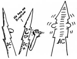
Transformers use a principle known as magnetic induction, and they operate much like the transmission in an automobile. If you've ever watched Mr. Wizard on TV, you've surely seen an electromagnet. Unlike the permanent magnets that some people stick on their refrigerator, an electromagnet consists of a coil of wire wound around a piece of iron or steel. When an electric current is applied to the ends of the wire, the iron core becomes magnetized. And when the electricity is removed the magnetism disappears.
It should come as no surprise that the exact opposite holds true as well - if you magnetize the iron, then electricity will be developed in the wire. In fact, this is how electric generators in a power plant work. But in order for a voltage to be produced, the magnetism must be constantly changing. That is, putting a coil of wire over a permanent magnet won't do a thing, except for the instant it's first put into place.
A transformer, therefore, requires AC to operate, and it is made up
of two coils of wire wrapped around a single piece of iron. When a constantly alternating
voltage is applied to one of the wires the iron will become magnetized, though the
magnet's polarity (North/South) will also change constantly. And while one of the coils is
creating the magnetism, the other will respond by generating electricity from it. But what
does this have to do with an auto transmission?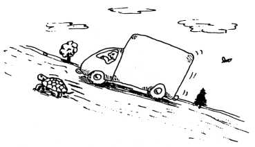
In a transmission, gears are used to vary the speed of your car, though at the expense of apparent power. That is, for a given amount of horsepower, you can either go slowly but with the ability to climb a steep hill, or go much faster as long as you stick to level terrain. Remember, the power doesn't really vary when you change gears, only the way that power is used. Nothing comes for free, and the transmission merely changes the way an engine's power is distributed.
In an identical manner, a transformer can transform a voltage that
is applied to one of the wires, to produce a higher or lower voltage in the other. The key
point here is the ratio between the number of windings in each coil. If one of the coils
consists of 200 turns of wire, and the other has only 100, then the ratio between them
will be two to one. And if you put ten volts into the larger coil, only five volts will
appear in the smaller one, though the available current will be twice as much. The actual
power always stays the same, and it's just the distribution that really changes.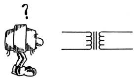
By the way, even when a circuit could operate on 115 volts directly, a transformer is often used just for safety. The very fact that the two windings are not really connected provides some degree of protection against being electrocuted.
SEMICONDUCTORS
One of the most significant developments of the twentieth century is
undoubtedly the semiconductor. These devices are nothing short of amazing, and without
them there would be no satellite TV, and no PCs. Most semiconductor devices these days are
made of silicon material, though you might occasionally find a diode or transistor made
from germanium. But what are they really, and how do they work?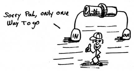
The simplest semiconductor of all is the diode, and it allows electricity to flow in only one direction. One obvious use might be to protect a portable radio if you accidentally install the battery backwards. Since a diode lets current travel in only one direction the radio would simply not operate, as opposed to being damaged. But a diode has many other important uses as well, and is the basis for a number of applications where AC must be converted to DC.
POWER SUPPLIES
All electronic circuits require some source of power in order to operate. For a digital watch or cell phone, that power comes from a battery. But for devices that connect to a wall outlet, some means of converting the 115 volts down to a level that the device can actually use must be provided. A power supply is the obvious solution, and it does a variety of other things in the process.
Though a transformer can adjust the voltage, most circuits will operate on DC only. So another conversion must also be performed. This is where the diode comes in, though in most power supplies at least two diodes are used. If only one diode is placed into an AC circuit, then only half of the available electricity will be used. Remember, half the time the electricity is going in one direction, and the other half it is reversed. So if a single diode is used the current passes only when the AC happens to be going in the favored direction, wasting the other half of the current flow.
There are many ways to construct a power supply, some using one
diode, some using two, and others using four or more. I don't see a lot of value in
belaboring all the possibilities, and I hope you'll understand if we move along to other,
more important aspects of power supplies. For example, regulation and filtering.
Once an AC voltage has been converted to its DC counterpart, the job is still not quite complete. Unless additional steps are taken, the voltage will still fluctuate. even though the direction is no longer changing. The original AC voltage is constantly varying in level gradually reaching a maximum, then progressing towards zero, and again approaching a maximum in the other direction. Therefore, even though the diode can block the voltage when it goes the wrong way, the level is still changing.
Earlier I mentioned that besides its frequency capabilities a capacitor can also be used to store electricity, much like a rechargeable battery. It is precisely this property that will help us out here. How much current can be stored, and for how long, depends on the size of the capacitor. But once an adequate value has been chosen, this capacitor will continue to supply voltage when the incoming level drops below its maximum. A power supply that uses capacitors this way is said to be filtered, though the purity of the DC that results depends on several factors.
The most important consideration is how much current is being drawn
by the powered device. That is, if the capacitor needs to provide only a small amount of
current, then it won't be depleted very much between cycles. Similarly, when a higher
frequency of AC input voltage is used, the capacitor won't have to provide the current for
as long. But no matter how large the capacitor is, some amount of fluctuation will still
occur. For circuits such as a PC that require a very stable voltage, the only real
solution is to employ regulation.
A voltage regulator is a fairly simple circuit, though again, I won’t go into great detail since it's just the principles that matter here. However, the general idea of a regulated supply is that it's capable of putting out slightly more power than is actually required, and uses some type of sensing circuit to constantly monitor its own output. When the powered circuit demands more juice, the sensor adjusts a built-in electronic valve to turn it up. Likewise, if the AC input varies - for example your air conditioner just kicked in - that can be compensated for as well.
So far we've assumed that a power transformer will be used to drop the original 115 volts down to something more manageable for the rest of the supply. But there's a problem with most transformers: they're big and heavy. Worse, the lower the frequency to be transformed, the more iron that is needed for the transformer to work efficiently. This is where switching supplies come in, and at last we're getting to something digital!
Since a computer's size and weight are sometimes as important as its speed, savvy designers will do everything possible to keep those to a minimum. Further, since electronic components are less expensive than copper and iron, a power supply that is twice as complex may still be cheaper to build if it can use a smaller transformer. With that in mind, let's look at how a switching power supply operates.
Most switching supplies begin with an extremely crude normal power supply. No regulation, minimal filtering, not even a transformer - it plugs right into the wall! Then, a circuit called an oscillator is connected to this "cheap" supply to create a new AC voltage, though at a much higher frequency. (The oscillators you may have encountered probably had a big dial, and produced a sweeping audio tone. The same idea applies here too, although the frequency is not adjustable.)
In this case the oscillator is used to rapidly switch the crude
supply on and off, thereby simulating an AC voltage. But the whole point is that since the
AC is artificially created, we can make it any frequency we'd like. And if we choose a
high enough frequency, only a very small amount of iron is needed in the transformer that
is ultimately required.
Another important reason many PC designers favor a switching power supply is because it also provides an improved means of regulation. As we saw earlier, all power supplies have the capability to put out slightly more power than is actually needed, with the slack being discarded by the circuits that sense the output voltage. However, an unfortunate side effect of throwing away the extra current is that it is always dissipated as heat, which also wastes power. But a switching supply can do this more intelligently, by varying the duty cycle of the AC voltage it creates.
Since creating AC from DC in a switching supply is simply a matter of turning the original power rapidly on and off, the relative times may be easily varied. That is, if the output voltage is sensed as being too high, then the "off" time can be made slightly longer. And when it falls too low, the "on" time is adjusted instead. The duty cycle of a power supply is always expressed as a percentage, with 50% meaning on for exactly half the time.
ON COMMON GROUND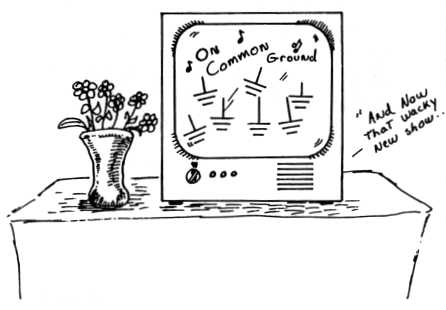
No, that's not the title for a new TV sit-com, but rather a means of minimizing the number of wires needed when building a piece of electronic equipment. Even though all circuits need two wires to operate, the same wires often end up going to a number of different places. In most personal computers, the negative wire coming from the main power supply is used as the common connection, and all other voltages are then referenced to it.
Many electronic devices are built inside some sort of metal box. Doing this serves not only to provide a solid mechanical structure, but also as a connecting point for any circuit that needs the negative wire from the power supply. As it turns out, a lot of circuits need that connection, so by first connecting the supply wire to the metal chassis, only a short wire from each circuit to the chassis is needed.
TRANSISTORS![]()
Transistors are made of the same silicon material that is used to create diodes, however they are slightly more complex internally. Most transistors are constructed in layers, with a piece of "P" material sandwiched between two other pieces of "N" material. (P and N refer to Positive and Negative.) The polarity of the silicon material is determined when it is manufactured, and this is something you'll just have to take for granted right now. By the way, some transistors are made in the reverse - two pieces of P surrounding a single N. But that's really not important. What is important, however, is the properties these materials possess.
Earlier in this discussion we used analogies to show how the flow of electricity is very much like the flow of water. And that's true. Though it was alluded to then, we didn't quite get around to comparing a water faucet with its electronic counterpart, which is a transistor. In fact, the British still refer to a vacuum tube - the transistor's predecessor - as a valve. Just as a 98 pound weakling can control hundreds of pounds of water pressure by merely turning a valve (well okay, a big valve), a transistor can likewise be coaxed into controlling a large amount of current by applying a smaller one to it.
 Most
transistors have three connecting wires, and the current to be controlled is attached to
two of them. The third wire is used for a control voltage, and it can regulate the amount
of electricity that flows between the other two. This is a very powerful concept, since a
small amount of current can be used to control a much larger one, which results in
amplification. By the way, the ratio of the amount of controlling current that is required
versus the amount being controlled is called a transistor's gain.
Armed with all of this knowledge, it's not very hard to see how a stereo phonograph works. A playback needle is attached to a tiny magnet, which is placed near a coil of wire that creates a voltage when the magnet moves. The coil is then attached to a transistor that controls the power from the power supply, which is connected to a speaker. And the knee bone's connected to the thigh bone, and the...
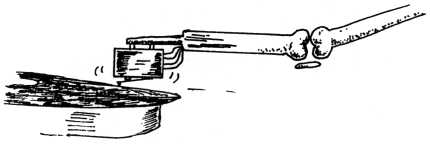
The more the phonograph needle wiggles, the more the loudspeaker at the end of the chain moves. And the faster the needle travels, then the faster the speaker moves. Simple, right? Right!
FEEDBACK
There's only one more thing to consider about the transistor, and that is the fact that its amplification of currents is less than ideal. Oh, you can be sure that as more and more current is applied to it, more and more will appear at the other end. But along the way, a nasty side-effect crops up, which is nonlinearity. This four-bit word actually describes a fairly simple problem, whereby the ratio between the controlling input and the output doesn't always stay fixed. When a small amount of voltage is put into a transistor, it will have more gain than for a larger voltage. With an audio amplifier, nonlinearity in the circuit creates distortion.
The underlying reason for this is quite complex, however the solution is very simple: negative feedback. Some examples of negative feedback in the home can be found inside a toilet tank, as well as in your oven. Suppose you're about to cook a frozen dinner. You'd go to the oven and set the thermostat for, say, 400 degrees. The heating coils begin to glow and remain on until the correct temperature is reached, at which point they will turn off. After a few minutes, as the oven begins to cool, the coils are again activated thus maintaining a constant temperature.
Earlier we saw how a power supply is designed to sense its own
output, so as to regulate the voltage that's produced. And as a circuit drew more and more
current (or if the air conditioner came on lowering the AC input voltage) the supply could
then adjust itself to produce more output. The same thing happens with an oven, only in
this case the thermostat does the sensing, and it controls the heating coils.
More sophisticated ovens use a proportional controller rather than simply turning the coils on and off. As the temperature drops, the voltage is increased; once it approaches the right amount, the voltage is decreased. But the whole point of all this is that it is possible for a circuit to control itself, by merely sampling some of its own output. The power supply needs to do this because the line voltage may drop, or the circuit being powered may demand more current. A transistor amplifier uses negative feedback to overcome its own inherent nonlinearity, though the principle is identical.
Now do you see why I mentioned a toilet? As the tank becomes full the float inside rises. And since the float is attached to the very valve that is filling the tank, a closed loop is formed. Same thing for those gadgets that control the speed of your car on a highway. Even constructive criticism could be considered a form of negative feedback - if enough of you wrote to complain about these ridiculous analogies, I'd probably stop using them! But seriously, all of these are legitimate examples of negative feedback.
 DIGITAL LOGIC CIRCUITS
All right, we've looked at analog electronics enough. While those are all important and useful topics, we should now move along and get down to some digital basics. We'll also look at schematic diagrams, the blueprints of electronic circuits.
Everyone knows that the real brains in a PC is its CPU, but what many don't understand is exactly how it works. While this tutorial can't replace a college level course, I will cover the important fundamentals. As usual, we'll start at the very beginning, which in this case is logic gates.
 RELAYS
Early digital logic circuits employed relays to perform all of the required functions. A relay is constructed from three very basic components: an electromagnet, a switch, and a spring. But where most switches are activated by pushing a button or throwing a lever, the switch (or switches) in a relay change state when voltage is applied to the coil of the electromagnet. The voltage causes the iron core to become magnetized, which then pulls the metal switch contacts into position. And when the voltage is removed, the spring takes over and pulls the contacts back. Many relays contain at least two switches, though some have as many as four or more, offering a wide range of possible circuit combinations.

Since drawing a realistic picture of an electronic component is not always the most efficient way to convey a circuit, electronic engineers instead use a schematic diagram. Most schematic representations are really pretty close to what an equivalent picture might look like, and a relay is shown both ways for you to compare.
Figure 1 shows the schematic for a single-pole (one switch) double-throw relay. The term double-throw means that one element - called the common - will be connected to either of two possible contacts: normally open, or normally closed. That is, when the relay is at rest with no voltage applied to its coil, the common contact is connected to the normally closed contact. And when the relay is activated, the common will be connected to the normally open one instead.

One of the basic logic functions that a relay can perform is called a latch, which is shown in Figure 2. A latch is used to allow a "push to start" type of operation, for example in most microwave ovens. Without it, you'd have to stand there and hold the button for the entire time it's cooking. Sure, you could use a regular toggle switch instead, but then how would the oven be able to turn itself off after five minutes?
Here, a double-pole double-throw relay is needed, since one of the
switches is required just to perform the latching function, and the other (not shown) can
then do whatever you want. When the pushbutton switch is pressed the coil is energized by
the power supply, causing both switches to change state.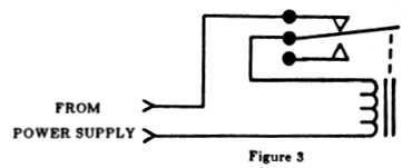
Notice, however, that the lower set of contacts is connected in parallel with the pushbutton switch, thereby maintaining power to the coil after the button is released. The relay will stay in this activated state so long as the power source is not interrupted. Incidentally, you could consider this latching action to be a form of positive feedback, since the output is being used to reinforce the input.
Negative feedback can also be applied to a relay's operation, as
shown in Figure 3. This oscillator circuit - commonly known as a buzzer - is created by
wiring the switch contacts in series with the coil. When power is applied the coil will be
energized, which causes the switch to change. Of course, the moment this happens power to
the coil is interrupted, and the spring pulls the switch contacts back to a normal state.
But this activates the coil all over again, and the process continues to repeat
indefinitely. I realize this is pretty basic stuff, but then so are most logic circuits.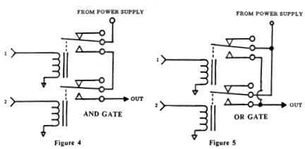
One of the most primitive logic building blocks is the gate, of
which there are several types. Figures 4, 5, and 6 show relay circuits for AND, OR, and
EXCLUSIVE OR gates respectively, and we're about to see how these terms came to be applied
to programming. Of course, most logic circuits don't use a set of switch contacts for
their output, but instead provide either of two possible voltages: the full power supply
or nothing. That's why each of these logic circuits are shown with a connection to the
supply.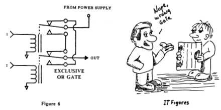
Beginning with the AND gate, if inputs 1 and 2 are powered, then the output will be powered, or One. Otherwise it will be off or Zero. For the OR gate, if input 1 or 2 is high, then the output will be One. All an EXCLUSIVE OR gate cares about is whether the inputs are different, providing a One output when they are. As you can see, a gate can be used to make simple decisions, based on the information at its inputs.
Regardless of which type of gate is being considered, though, its output is always determined by the signals at its input. As you just learned, there are three different categories of gates: the AND gate, the OR gate, and the EXCLUSIVE OR. Inverted versions are also available, called NAND (which means NOT AND), NOR, and EXCLUSIVE NOR.
 Where the schematic diagrams we've looked at show precisely how
each relay is connected, the logic diagrams in Figure 7 are more appropriate for their
solid state equivalents. And though each of the gates is shown with only two inputs, IC
(integrated circuit) gates are available with up to eight or more inputs. Under each
symbol is a truth table showing what happens at the output for each possible
input combination. The inverted gates (NAND, NOR, X-NOR) are shown in Figure 8.
Relay gates employ a mechanical switch, though a solid state gate instead uses transistors. Remember, all transistors use a control voltage on one of the wires, to control the flow of electricity through the other two. Therefore, it is not difficult to simulate the action of a relay electronically.
Like diodes and transistors, an integrated circuit chip is also constructed from silicon and arranged in layers, though it is of course considerably more complex. Internally, an IC contains many individual transistors, diodes, resistors, and capacitors. All of the various components are interconnected when it is manufactured, which takes place in a "clean room" where the workers wear special clothing to prevent hair and dust from getting into these tiny and delicate devices.
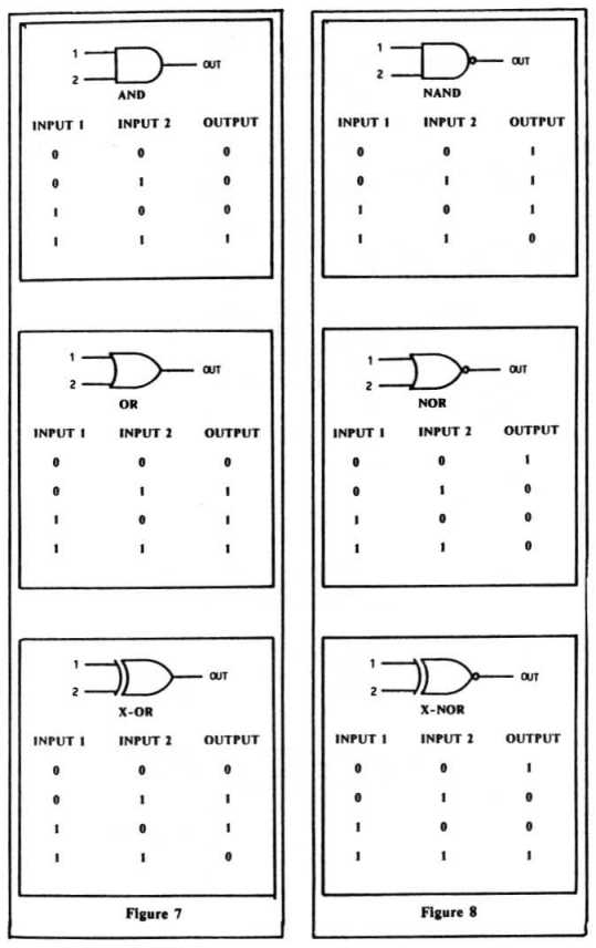
Inverted (NOT) versions of these gates operate in essentially the same manner as the non-inverted types, with the output polarity simply reversed. The little circle on the right in each drawing indicates the inversion, meaning the output will be "not one" when the normal input requirements have been met.
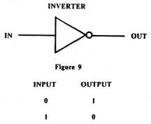
This doesn't require an engineer to maintain a separate family of parts, because once you think about it, a positive AND gate is the same as a negative NOR gate, and vice versa. The only real difference between a positive and a negative gate is that the negative ones have an inverter at their output. An inverter is really the simplest circuit of all, and merely converts a One to a Zero, and a Zero to a One, as shown in Figure 9.
 While
it may seem difficult to believe, a computer's CPU is created solely from a collection of
these gates, though of course many of them are required. Other, simpler circuits can also
be derived from logic gates, so we'll continue our discussion with those.
COUNTERS
Solid state counters have a variety of applications in the real world, for example the electronic stop watches used at a sporting event. Figure 10 shows a binary counter, again as a standard logic diagram. Even though this particular device can count only to 16, it is not hard to see how the principle can be extended to allow counting to any reasonable number.
By the way, digital logic circuits are not specified in the same way as resistors and capacitors, since they don't have an actual "value." They are instead assigned part numbers by their manufacturer, and this particular counter is called a 7493. Here's how it works.
Besides the mandatory connections to the power supply, the 7493 also has two inputs and four outputs. One of the inputs is used simply to reset the count (all outputs zero), and the other is used as a "clock" to increment the count. That is, each time the clock input wire receives a momentary signal, the various outputs change.
The first time a clock pulse is received at the input, output number
1 will go high. The next clock causes output number 2 to go high, though at the same time
output number 1 goes low. Remember, this is a binary counter, and each output wire
represents a single bit of a complete number. The next clock that comes along will cause
output number 1 to go high again, and the next one sets output 3, while clearing outputs 1
and 2. This continues until all of the outputs are set to one, though at the next
occurrence of a clock input the count "wraps" around to begin all over again at
zero.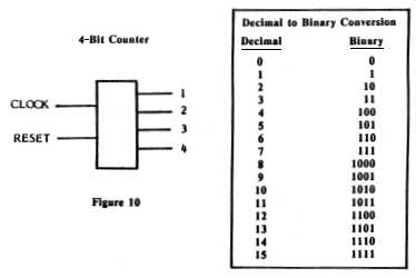
As I mentioned before, all logic devices such as this counter are ultimately built from nothing more than gates. Though we don't really need to cover every logic device in such detail, other IC chips are available for performing a variety of different functions. Some of these are frequency dividers, whose output changes state for every other input clock signal, and shift registers that can pass a single bit through a long series of sequential stages.
For the 7493 in Figure 10, a separate output wire is used for each of the bits being counted. This type of set-up is called parallel, since all of the outputs are available simultaneously. Other devices are designed to operate in a serial fashion, where a single wire is used to sequentially carry a series of ones and zeroes. Can you see a similarity to the parallel and serial ports on a personal computer?
Because a serial system uses a single pair of wires, it is course much slower than an equivalent parallel system, where all of the bits are sent at one time. This doesn't really matter with printers, though, because they're so much slower than a PC to begin with. And with a modem we don't have a choice, because the signals must travel down the phone line which has only two wires. But disk controllers, memory chips, and most of the other circuits in your PC always use a parallel system, often called a bus, to carry the various signal around.
Another important consideration when dealing with solid state IC logic chips is their propagation delay. This term refers to how long it takes for the proper outputs to appear, once the inputs have been set. Or to put it another way, how long it takes the electricity to travel through it. Usually, propagation time is measured in nanoseconds, which of course is very short. But when you're trying to get a computer to run at 500 MHz. every nanosecond counts.
The RAM chips used for a PC's memory also have some minimum response
time. When the CPU requests a byte of information from memory, a slight delay before the
chips can respond is inevitable. So when an IC chip is rated at 50 nanoseconds (or
whatever), what is really being described is how long it takes to respond.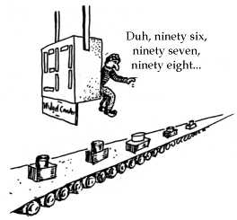
Without wanting to get too far off the beaten path, it may be worth mentioning the cause for these inevitable delays, which is stray capacitance and inductance. Just as a capacitor is created by placing two pieces of metal in close proximity, some small amount of capacitance also results even when the pieces are farther apart. And the same phenomenon applies to inductance, too. Where most inductors are created by placing a length of wire into a coil, a straight piece used just for the various interconnections exhibits some inductance as well. Therefore, all of the wires and circuits in a PC and its chips have tiny amounts of inductance and capacitance, and the resultant frequency characteristics tend to slow things down.
By the way, when we talk about the speed of a computer as being a number of Megahertz, what is really being considered is its clock frequency. A 300 Megahertz clock speed means that a new signal is being generated 300 million times per second. Just like the 7493 counter chip that is incremented by one with each clock pulse that's applied, computers work the same way. That is, all of a CPU's internal operations happen in step with its built in clock.
The next important area of digital circuit design is the central processor itself, which is considerably beyond what we can discuss here. However, I would like to recommend some additional resources for learning about electronics and computer circuits.
All IC and component manufacturers provide literature about their
products, but some go far beyond that giving complete working example circuits. While most
of the catalogs are of course targeted at professional engineers, the books put out by
National Semiconductor are outstanding in both content and clarity. In fact, their Linear
Applications Handbook has a complete course describing how color TV works, besides many
other tutorials and build-it projects. When I got mine a number of years ago, they were
provided for free if you could convince the local sales rep that you're actually a
potential buyer. But even at $10 or whatever they list for now, they're still a real
bargain.
Another useful publication is the Radio Amateur's Handbook, which is published by the American Radio Relay League and is usually sold in electronics stores. Though the emphasis is plainly on ham radio and related subjects, it too provides a great deal of information for the money. It also begins at a better level for most beginners than the National manuals. In fact, ham clubs are a good source too, even if you have no real interest in radio. Like most PC clubs, the members are usually very friendly and eager to share what they know with anyone who takes the time to ask.
I would like to extend special thanks to Bill Eppler, who has contributed enormously to my understanding of electronics and circuit theory over the years.
Text edited and revised April, 1999
Drawings Copyright © 1987 Jay Munro.
Entire contents of this web site Copyright © 1997-
by Ethan Winer. All rights reserved.