
| www.ethanwiner.com - since 1997 |
Build a Microphone Polarity Tester
by Ethan Winer
This article is from the May 1997 issue of Recording magazine
Many things can go wrong in a modern recording studio, but few are as difficult to track down as reversed microphone polarity. When a microphone is placed in front of a sound source, a positive pressure on its diaphragm caused by forward-moving air results in a positive voltage on one of its output pins and a negative voltage on the other. But which pin is positive? These days most microphones have XLR output connectors, with Pin 2 used for the positive voltage output and Pin 3 for the negative. But you can't always count on this, especially if the microphone is an older model, or was ever repaired or otherwise rewired.
When a single microphone is used to capture an instrument or voice, the absolute polarity of its output doesn't really matter. But it is common to use two microphones, especially with larger instruments such as a piano or maybe a small string section. If you're using a pair of identical microphones it isn't likely they'll be wired differently. However, many engineers like to use two different types of microphones, for example when recording an acoustic guitar or perhaps a cello. One common technique is to place one of the mikes relatively close to the instrument and the other several feet away. Another method places both microphones close to the sound source, but with each aimed at different places on the instrument.
When two microphones are used to record a single sound source it is imperative that they respond to a forward pressure on their diaphragms in the same way. If the polarity of one of the mikes is reversed, the tone will become very thin and lack bass when the two outputs are mixed together. Even if the mikes are panned hard left and right for a stereo effect, if their polarity is not consistent the sound will appear to be unfocused and vague, and difficult to localize in the stereo sound field.
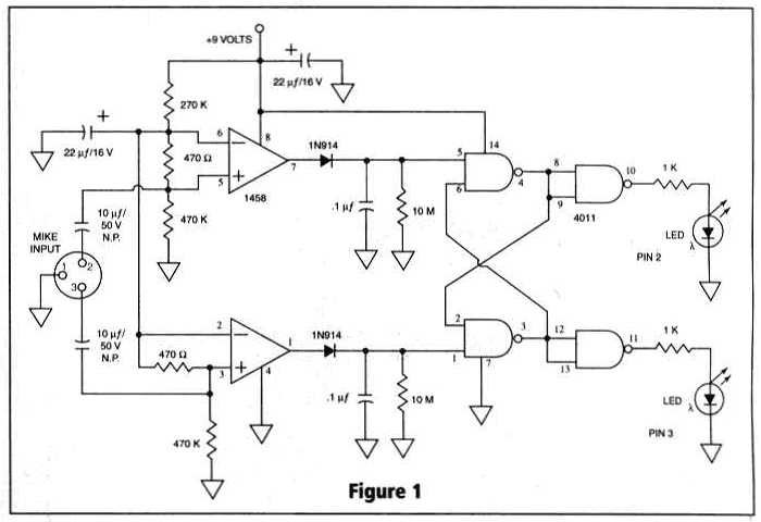
It's a simple matter to determine the absolute polarity of most studio equipment using an oscilloscope. By feeding a pulse wave into the device and monitoring the input and output signals simultaneously, you can quickly see if the polarity is the same or reversed. Unfortunately, there is no easy way to know the absolute output polarity of a microphone. To solve this problem I designed the microphone polarity tester described here. This handy gadget is comprised of two components: a "pulser" that sends a forward-moving pulse through a small loudspeaker, and a detector circuit that determines which of the microphone's output pins presents a positive voltage in response to that test pulse. You simply aim the microphone at the tester's built-in speaker, and press the Test button. One of the LED indicators corresponding to Pin 2 or Pin 3 then lights up to indicate which output pin is positive.
Battery operation makes the tester portable and nearly pocket size, and you can optionally add a pair of 22-1/2 volt camera batteries to provide phantom power for condenser microphones. These batteries are about the size of a standard AA cell, and they will last for years since they are used for only five or ten seconds at a time. Without the extra batteries you will need an outboard power supply to test condenser mikes that require phantom power.
HOW IT WORKS
When the push-button switch is pressed, a brief voltage pulse is applied to a small loudspeaker which is used as the "sender." By connecting the speaker's Plus terminal (marked with a red dot or "+" symbol) as shown in the schematic in Figure 2, the speaker diaphragm will jump forward creating an increase in pressure in front of the mike being tested. The microphone's output pins are routed to a detector circuit that remembers which pin went positive first. It's not sufficient to merely read which pin goes positive, because all mechanical devices continue to vibrate, or ring, after the application of a single pulse. Since a certain amount of ringing is inevitable in all loudspeakers and microphones--even very expensive models--the mike under test will respond to the speaker's pulse by outputting several complete voltage cycles. Thus, the tester must determine not only which output pin went positive, but which went positive first. A digital "lock-out" circuit disables the second LED once the first one has lit.
CONSTRUCTION
All of the parts used in this project are inexpensive and readily available, and I have provided Radio Shack part numbers for everything. If you already have a supply of common resistors, capacitors and other assorted components, the total parts cost should less than $25. Because the circuitry is fairly simple (see Figure 1), I hand-wired the various parts on a piece of perforated construction board. Each component's wires are pushed through the pre-drilled holes, and those wires are then routed to and wrapped around the other component leads according to the schematic. This is shown in the accompanying photograph.
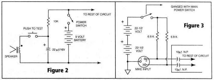
You may want to buy a slightly larger case than the one specified, especially if you haven't built many electronic projects before. The small case I used requires that you pack the various components fairly tightly. Further, if you decide to add the optional phantom power batteries as shown in Figure 3, you will have to use a larger enclosure. You should attach the speaker to the plastic case using a thin bead of contact (not rubber) cement applied to both the speaker's gasket and the inside of the case. Be sure to let the cement dry for at least five minutes before pushing the pieces together. And, of course, you must drill 1/8th inch sound holes in the case before mounting the speaker!
CHECKOUT AND USE
When the power switch is first turned on, one of the LEDs will light up for a few seconds and then go out after the capacitors charge and the voltages have stabilized. If you have a phantom supply connected or are using batteries for that, it will take a bit longer for the LED to go out. Plug in the microphone to be tested and aim it at the tester's speaker getting as close as necessary to obtain an indication. Most dynamic microphones must be within an inch or two of the speaker; many condenser models have a higher output level and don't need to be that close. Be assured, however, that the tester will never give a wrong answer (assuming you built it correctly), since neither LED will light if the mike isn't close enough.
PARTS LIST
Plastic case, 4-3/4" x 2-9/16" x
1-9/16"; RS# 270-222
Perforated circuit board, 0.1" grid spacing; RS# 276-1395
2-1/4" miniature speaker; RS# 40-246
9-volt rectangular battery; RS# 23-553
9-volt battery clip with wires; RS# 270-324
XLR connector, 3-pin female; RS# 274-013
Push-button switch, momentary SPST; RS# 275-618
Miniature toggle switch; RS# 275-634
2 pcs. 470 ohm 1/4 watt 5% resistor; RS# 271-1317
2 pcs. 1K 1/4 watt 5% resistor; RS# 271-1321
1 pc. 10K 1/4 watt 5% resistor; RS# 271-1335
1 pc. 270K 1/4 watt 5% resistor; RS# RSU-11345337
2 pcs. 470K 1/4 watt 5% resistor; RS# 271-1354
2 pcs. 10M 1/4 watt 5% resistor; RS# 271-1365
2 pcs. 0.1 uF. mylar capacitor; RS# 272-1069
2 pcs. 10 uF. 50-volt non-polar electrolytic capacitor; RS# 272-999
3 pcs. 22 uF. 16-volt electrolytic capacitor; RS# RSU-11296860
2 pcs. 1N914 silicon diodes; RS# 276-1122
2 pcs. standard size (1/4 inch) LED; RS# 276-066
2 pcs. LED mounting clip; RS# 276-079
1 pc. 1458 dual op-amp; RS# 276-038
1 pc. 4011 CMOS quad gate; RS# 276-2411
For optional phantom powering:
2 pcs. 22-1/2 volt battery; RS# 23-510
2 pcs. 6.8K resistor; RS# RSU-11345030
Use toggle switch RS# 275-636 instead of 275-634
Entire contents of this web site Copyright © 1997- by Ethan Winer. All rights reserved.