| www.ethanwiner.com - since 1997 |
|
Pre-Distortion
Techniques
Build a Tape Linearizer and a Distortion Analyzer
by Ethan Winer
This article first appeared in the December
1981 issue of Recording-engineer/producer magazine.
No sane recording engineer would ever add distortion to
a program intentionally - unless, of course, the goal was to increase headroom and lower
tape distortion. No, I'm not talking about a new type of "sonic exciter," but a
well-known and accepted method to counteract the onset of saturation in analog recording
tape. Unlike amplifiers or other electronic circuits for which the clipping threshold is
well defined, analog tape distortion creeps up slowly, minimizing dynamic range and
blurring transients. By using a tape linearizer - a circuit included in recorders by such
manufacturers as Scully and MCI - it is possible to reduce distortion in the range above 0
VU, while raising the level at which third-harmonic distortion (THD) reaches 3%. (The 3%
point is a standard reference level.)
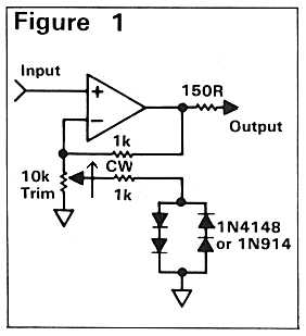 The pre-distortion circuit
described here is extremely simple (Figure 1) and only requires one trimmer adjustment,
though you'll need an accurate way to measure THD in order to achieve the best results. A
dedicated distortion analyzer to help you adjust the linearizer circuit is shown later in
this article. This analyzer has turned out to be one of the most useful little gadgets I
have, given its simplicity and incredibly low price. The only thing keeping it from being
lab quality is that it uses switched rather than continuously tuned frequencies.
Therefore, you must adjust your sine wave generator to match its frequencies, rather than
the other way around. But since most oscillators can be set to produce any audible
frequency, this is a relatively minor limitation. For example, on my prototype the 1 KHz
position turned out to be 960 Hz, and the 10 KHz setting was more like 9.7 KHz.
The pre-distortion circuit
described here is extremely simple (Figure 1) and only requires one trimmer adjustment,
though you'll need an accurate way to measure THD in order to achieve the best results. A
dedicated distortion analyzer to help you adjust the linearizer circuit is shown later in
this article. This analyzer has turned out to be one of the most useful little gadgets I
have, given its simplicity and incredibly low price. The only thing keeping it from being
lab quality is that it uses switched rather than continuously tuned frequencies.
Therefore, you must adjust your sine wave generator to match its frequencies, rather than
the other way around. But since most oscillators can be set to produce any audible
frequency, this is a relatively minor limitation. For example, on my prototype the 1 KHz
position turned out to be 960 Hz, and the 10 KHz setting was more like 9.7 KHz.
WHAT IS PRE-DISTORTION?
When audio is recorded onto analog tape at high levels,
the tops and bottoms of the signal are compressed or clipped as the magnetic material
approaches saturation. The pre-distortion scheme provides a slight increase in gain at the
very extremes of the waveform, to overdrive the tape just enough to offset the
flattening that occurs normally. This non-linear amplification by itself produces a
distortion that is similar, though opposite, to that of the tape; hence the term
pre-distortion.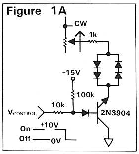
The circuit in Figure 1 provides the required increase
in gain as the signal reaches a certain level, dependent upon the setting of the 10k
trimmer. Normally, the gain of an op-amp is determined by the ratio of the resistors in
the feedback voltage divider. But in this circuit the diodes become active as the voltage
across them reaches 1.2 volts. This effectively lowers the resistance of the 10k trimpot
on signal peaks thus increasing the gain. Separate diodes are required for each polarity
to create a symmetrical response, since tape distortion occurs at both the positive and
negative extremes.
If you aren't afraid of modifying your recorder (and
you shouldn't be), an even simpler implementation may be used requiring only two diodes,
the trimmer, and an electrolytic capacitor. Figure 2 shows a typical record output stage
as found, for example, in Ampex and MCI machines. Figure 3 illustrates the addition of the
pre-distortion components. Simply replace the emitter resistor of the bottom transistor
with a trim-pot of similar value, and add a capacitor and the diodes as shown. Because the
signal voltage at this point in the circuit is relatively small, only one pair of diodes
is required. These should be germanium types such as the 1N34 or 1N270, since their
reduced turn-on threshold more closely coincides with these low levels. Other recorders,
such as ReVox and Scully models, employ a single output transistor. The emitter resistor
still controls the gain, however, and the modification is the same. In the unlikely event
that you encounter a PNP transistor, you should reverse the polarity of the capacitor.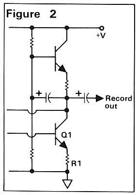
There is no reason to believe that this method would
not improve the performance of a cassette deck as well, although the optimum place to tap
into the circuit is after the pre-emphasis networks. The biggest appeal for pre-distortion
is when recording at 30 IPS without noise reduction, since every clean dB you can squeeze
onto the tape is important.
If you use the op-amp circuit of Figure 1, rather than
modify the record electronics of your machine you might allow switching out the distortion
circuit since it affects the audio quality when monitoring through the recorder's input.
You can either add a switch that disconnects the diodes from ground, or use a transistor
switch (Figure 1A) which allows automatic operation via the record relay. A transistor
switch also lets you control many channels from one mechanical switch.
At first glance the switching transistor appears to be
connected backwards, but this is not a mistake. Although the gain of a transistor is very
low with collector and emitter transposed, this is better for switching audio since the
diodes are brought much closer to ground. If 10 volts is inconvenient as a control, any
other voltage can be accommodated by changing the 10k resistor up or down using about 1k
for each volt of input. Also, a PNP transistor should be used if the control voltage will
be negative.
It is also possible to use this circuit to provide
post-distortion on playback to improve tapes that were already recorded too hot. A few
years ago, a cassette manufacturer introduced a model with this feature, although I
suspect that proper adjustment is quite difficult. Speaking of adjustment, it is
imperative to have some means of measuring THD for this project to be a success, which
brings us to the next part of this article.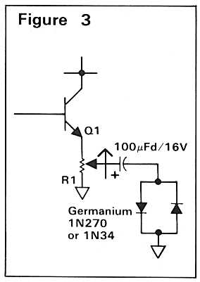
THE DISTORTION ANALYZER
At the heart of any THD meter is a notch filter that
can completely remove the original test frequency. After filtering, it is an easy task to
measure the harmonics and noise that remain, and relate them to the total signal as a
percentage. It also helps to have an oscilloscope connected to the notch-filter output, so
you can see the exact nature of the distortion. Listening to the output of the filter is
useful too and recommended.
During the course of testing the pre-distortion circuit
on my Otari MX-5050B recorder, I measured nearly 1% distortion through the electronics
only when the input level reached +10 dBV. With an oscilloscope I could see this was
mostly second harmonic, which I later pinned down to the output transformers. (More about
this later.) Of course, the tape distortion at this level was almost 3%, but being mostly
third harmonic, it won't necessarily mask the recorder's distortion. With the linearizer
circuit connected and adjusted for the best results, I was able to reduce the 3% figure to
just above 1% using Ampex 456 Grand Master tape. (For reference, 0 VU on my Otari
corresponds to 200 nW/m flux level.)
When measuring distortion, it is important to start
with a clean test signal. An inexpensive function generator is not adequate, even if a
sine wave output is provided. One percent THD is typical for these units, although that
can be reduced to 0.1% by applying 20 dB of peak boost with a parametric equalizer. This
procedure is most effective at low and middle frequencies; shelving off the high-end at an
appropriate point can further reduce distortion. I use a Heathkit Model IG-18 sine wave
generator, which uses a bridged-T RC oscillator yielding about 0.1% distortion. Routing
the output through a parametric equalizer then gives me a very clean signal for my tests.
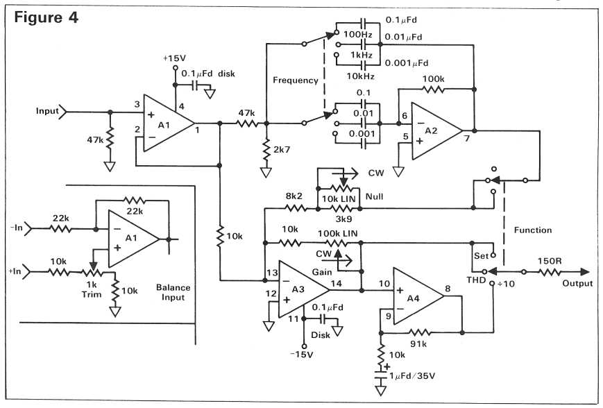
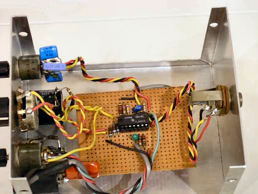
Figure 4 shows the distortion analyzer schematic, and the photograph shows how the
parts are mounted on one tiny circuit board. In fact, building the analyzer circuit was
easy - it's the pots and switches, the drilling and labeling, and making a power supply
that's a pain! If you build a lot of little gadgets in metal boxes, you can save the
expense and trouble of constructing a separate power supply for each by instead using a
1/4-inch stereo jack as a power connector. This way, one power supply can power many
different projects. This also allows some distance to be placed between sensitive circuits
and the power transformer's hum field.
Referring to Figure 4, input buffer op-amp A1 has a
gain of unity, and is used solely to isolate the active filter from the outside world. If
a balanced input is needed, use the alternate version shown in the inset. The 1k trimmer
adjusts common-mode rejection, though it may be easier to simply use precision 10k
resistors instead and omit the trimpot. A2 is configured as an active bandpass filter
whose frequency is determined by the switch-selected capacitors. This filter has a
bandwidth Q of 3, and produces a notch when its input and output are summed together at
A3.
You can choose any audio frequency by scaling the
capacitors up or down, using the values given as a guide. For example, a value of 500 pF.
yields a 20 KHz filter, and 0.2 uF. tunes it to 50 Hz. The capacitors should be
high-quality mylar or mica types, and avoid the more common disk ceramic units that are
temperature sensitive. Adjustment for THD measurement is very delicate, and even a tiny
amount of frequency drift will be a real handicap. For this same reason, the null
potentiometer should be a 10-turn wirewound device if possible, or at least use a large
knob to help increase resolution.
The actual frequency cancellation occurs at the
inverting input of A3 when the function switch is set to THD. The gain control
sets the full scale to 100%, and A4 provides an additional 20 dB of gain for measuring
very low distortion levels. When used with a meter that can measure in millivolts, this
circuit allows readings below 0.01% with confidence. Use a TL074 quad op-amp and not the
lower cost TL084, since the latter's higher noise level may limit the minimum obtainable
reading.
Ground loops are another important consideration
whenever small signals are involved, since any hum or high-frequency noise on the ground
wires shows up on the meter as distortion. This is another reason for using an
oscilloscope or audible monitoring of the output while measuring.
One way to ensure that the analyzer itself has no
internal grounding problems is to bring the input, output, and power grounds together at
only one point on the circuit board. Toward this end, an insulated jack (for example,
Switchcraft N-112A) is used for the input connector to prevent the metal case from
bridging the jack grounds. If you are a real stickler for accuracy you should trim the
gain of A4 to be exactly 20 dB, since this amplifier stage is in the measurement path. You
can do this either with a trim-pot, or by using precision resistors.
SETUP AND USE
Once you've completed building the unit, plug it in,
turn it on, and pray it doesn't blow up! If it passes the smoke test, take a voltmeter and
check each op-amp's output pin - these are conveniently located in the corners of the IC.
The DC voltage should be within a few millivolts of ground; if it is not check your wiring
and/or try another IC. Now you are ready to begin measuring distortion. The first thing to
measure should be your sine wave oscillator, so connect it to the analyzer's input.
Start with the output frequency set to 1 KHz, the
function selector to Set, the null pot in the middle, and the analyzer's gain
control at minimum. Now adjust the oscillator to some reasonable output level, and
increase the analyzer's gain control until its output reads 10 volts on an AC meter. (Note
that many digital multi-meters do not have a frequency response that extends beyond a few
KHz, so an analog meter is a better choice. Also, since the test procedure involves
nulling, a mechanical meter is much easier to interpret.)
With the full-scale set at 10 volts, switch the
function selector to THD, and alternately adjust the null pot and the
oscillator's frequency to obtain the minimum reading possible. Now select the Divide
by 10 switch setting and continue tweaking until you are satisfied that you have
completely canceled the 1 KHz fundamental tone. You are now reading distortion directly in
percent - that is, 10 volts equals 10%, 0.1 volt equals 0.1%, and so on. You will probably
find that due to capacitor tolerances, the 1 KHz setting is not precisely 1,000 Hz. Again,
it doesn't really matter, but you should make note of the actual frequency to save time in
the future. Try the same thing at 100 Hz and at 10 KHz (or whatever you choose), and
you'll be an old pro in no time at all.
Measuring distortion while the tape is running follows
the same basic procedure, although two new factors have to be dealt with. First of all,
any wow or flutter in the recorder will modulate the test frequency and, if severe enough,
can make nulling impossible. This isn't as much of a concern with professional recorders,
so we'll move along to the next problem. One of the most powerful uses for a distortion
analyzer is to help optimize tape bias. In the October, 1978 issue of R-e/p (Your
Studio Mastering Tape) authors Ball and Dahl illustrate that the best bias point for
Ampex 456 or 3M 250 is when the third harmonic distortion is at a minimum. The only
problem trying to measure this is that as the bias is increased, the overall output level
from the tape decreases along with the harmonic components. You can easily be seduced into
thinking that distortion is at a minimum when, in fact, the actual value in percent may be
relatively high. If you have a dual-trace oscilloscope simply view the analyzer's input
and output simultaneously with the patterns superimposed. As the level goes up and down
with variations in bias, both patterns will grow and shrink making it easy to visualize
the ratio between them.
Another method is to feed the output of the recorder
into a low-distortion limiter before routing it to the analyzer. Use a moderate to slow
release time, and just enough limiting to hold the level constant. You should try this
first without the recorder, just to be sure that your limiter has low enough distortion by
itself. By the way, bias adjustments should be done with 1 KHz at a level near 0 VU. Once
the bias is correctly adjusted, the next step is to add pre-distortion.
With the linearizer circuit in place and its 10k
trim-pot at minimum, begin recording a 1 KHz tone while monitoring off the tape. Increase
the input level until the measured distortion reaches 3% and then slowly advance the
trimmer. The distortion reading will start to dip as the diodes engage, and it will be
obvious when you have found the optimum setting. That's all there is to it, although this
adjustment should be checked from time to time, along with the usual alignment procedure.
Honesty compels me to point out that one important
difference between this distortion analyzer and a "real" one - besides
tunability - is the lack of automatic nulling. Although earlier units by Hewlett-Packard
and other manufacturers were very similar to this one, current models are capable of
automatically adjusting themselves for the most complete cancellation. Of course, this
doesn't improve the overall accuracy, but it certainly is more convenient! Bear in mind,
this analyzer is cheap to build and you get what you pay for.
TRANSFORMERS
I know it may seem a little late to be jumping on the
"transformerless" wagon, but two recent experiences really brought this home.
[Remember, this was written in 1981.] Earlier I mentioned tracking down 1% THD to the
transformers in my Otari tape recorder, and when I bypassed them the distortion at +12 dBm
dropped from 1.1% to 0.13% - a nearly ten-fold improvement. The overall output level
dropped by several dB too, but that's a small price to pay for improved audio clarity.
This was one of the easiest modifications I ever made since the Otari's transformers are
mounted on their own circuit board right next to the output connectors. If you make this
mod you can cut and splice the connecting wires to bypass the board, but pay attention to
the plus and minus signs to preserve signal polarity. I only wish the next problem was so
easy.
I recently had the opportunity to compare a new,
state-of-the-art transformerless mike preamp side by side with the transformer inputs in
my home-made console. The difference was astonishing and I was determined to find out why.
The first test I tried was low-level frequency response through the transformer input. Not
bad so far: down 0.5 dB at 20 KHz, but still respectable. Of course, music does not
consist solely of static sine waves so the next test was square waves. The steep slopes
are rich in harmonics, and its repetitive nature makes viewing on an oscilloscope a lot
easier than music. At 1 KHz, the oscilloscope trace looked nearly ideal, with only a
slight rounding of the corners corresponding to the high-end roll off. At 10 KHz things
were still looking good, although the rounding was becoming more pronounced. At 30 KHz,
the whole picture changed as the rounded edges became contorted trapezoids reminiscent of
slew-rate limiting. Clearly this was a problem, since cymbals and bells can produce
substantial energy at frequencies beyond 20 KHz.
Although simple harmonic distortion might not be an
issue way up there, audible intermodulation products can be created. A few years back I
connected my tube U-47 to an H-P spectrum analyzer, and was astonished to see a straight
line to its 50 KHz measurement limit as I jiggled my key ring in front of the capsule.
High frequencies do occur in nature, and a good mike will pick them up!
However, this story is not meant as an indictment of
all audio transformers. First, all transformers are not this bad, and in fact I chuckle as
I look back on my own naivete, since those transformers were quite expensive. I guess you don't
always get what you pay for after all! Second, it is not uncommon to find a transformer
included within the feedback loop of an amplifier, thereby overcoming much of its inherent
distortion. And finally, the oscilloscope photos that I've seen in ads for Jensen
transformers are truly outstanding, implying far superior performance to my thumb-size
imports. Needless to say, I am currently hard at work on a new input stage for my console,
and will report my findings in a future article.
RECOMMENDED READING
How to Select and Treat a Mate - Your Studio
Mastering Tape, by J. Talmage Ball and W. Jeffry Dahl; R-e/p, October, 1978.
Audio From the Magnetic Recorder's Point of View,
by David R. McClurg, R-e/p, October, 1976.
Performance Limits in Contemporary Console Design,
by John Roberts; R-e/p, April, 1980.
ACKNOWLEDGEMENT
Once again, I'd like to thank Bill Eppler for helping
me to sound intelligent.
Entire contents of this web site Copyright ©
1997- by Ethan Winer. All rights reserved.