TABLE OF CONTENTS |
|
Acoustic
Treatment and Design for
Recording Studios and Listening Rooms
by Ethan Winer
Ethan's book The Audio Expert explains |
Ethan Winer is co-founder of RealTraps, a leading manufacturer of acoustic treatment products. Ethan has at various times earned a living as a professional musician, computer programmer, circuit designer, recording engineer, composer/arranger, technical writer, acoustician, and college instructor. Ethan has more than 200 feature articles published in various computer and audio magazines. He’s produced dozens of educational and music videos, and composed three pieces for full orchestra, all of which have been performed. A shorter, and much simpler, version of this document is on the RealTraps web site.
If you have questions about anything in this article, or anything else related to audio, you're welcome to ask in my Audio Expert Forum.
This page was last updated on May 9, 2016.
French readers, see THIS version that is
being translated by Christian Parent.
Hungarian readers, see THIS
version that was kindly translated by Tamás Bánfi. Everything is included except the
sidebars.
Bulgarian readers can download THIS version
as a Word doc file, thanks to Borislav (Bobby) Mihaylov.
|
INTRODUCTION
TABLE OF CONTENTS |
|
I've been pleased to see the current growing interest in acoustic treatment. Even as recently as five years ago, it was rare to read a magazine article or newsgroup posting about acoustics, bass traps, diffusors, room modes, and so forth. Today such discussions are common. And well they should be - the acoustics of a recording or listening room are arguably more important than almost anything else!
These days, all gear is acceptably flat over the most important parts of the audio range. Distortion, aside from loudspeakers and microphones, is low enough to be inconsequential. And noise - a big problem with analog tape recorders - is now pretty much irrelevant with modern digital recording. Indeed, given the current high quality of even semi-pro audio gear, the real issue these days is your skill as a recording engineer and the quality of the rooms in which you record and make mixing decisions. Top
What's the point in buying a microphone preamp that is ruler flat from DC to microwaves when the acoustics in your control room create peaks and dips as large as 20 dB throughout the entire bass range? How important really are jitter artifacts 110 dB below the music when standing waves in your studio cause a huge hole at 80 Hz exactly where you placed a mike for the acoustic bass? Clearly, frequency response errors of this magnitude are an enormous problem, yet most studios and control rooms suffer from this defect. Worse, many studio owners have no idea their rooms have such a skewed response! Without knowing what your music really sounds like, it is difficult to produce a quality product, and even more difficult to create mixes that sound the same outside your control room.
This article explains the basic principles of acoustic treatment. Some of the material is taken from my bass traps plans published in Electronic Musician magazine, some is from my company's web site, and some is from my postings in audio newsgroups. However the vast majority is new content that does not appear anywhere else. I have consolidated this information here to provide a single comprehensive source that is free of commercial references. My goal is to offer advice that is complete and accurate, yet easy to understand using common sense explanations instead of math and formulas. Although many books about recording studio and listening room acoustics are available, most of the better ones are too technical for the average audio enthusiast to understand without effort. And you'd need to purchase and read many books to learn a few relevant items from each. All of the information herein applies equally to home theaters, small churches and auditoriums, and other rooms where high quality reproduction of audio and music is required. Top
This text will surely expand as I learn more. And as people ask me questions or request elaboration, I will incorporate the answers and additions here. Also, there is a growing list of acoustics Articles and Videos on my company's web site. If you have questions or comments about anything related to acoustics, please do not send me email. I prefer that you post publicly in whatever forum you know me from, or at my own Audio Expert forum. This way the effort I put into answering can help others, and you can benefit from the answers of others too. Top
There are four primary goals of acoustic treatment: 1) To prevent standing waves and acoustic interference from affecting the frequency response of recording studios and listening rooms; 2) to reduce modal ringing in small rooms and lower the reverb time in larger studios, churches, and auditoriums; 3) to absorb or diffuse sound in the room to avoid ringing and flutter echoes, and improve stereo imaging; and 4) to keep sound from leaking into or out of a room. That is, to prevent your music from disturbing the neighbors, and to keep the sound of passing trucks from getting into your microphones.
Please understand that acoustic treatment as described here is designed to control the sound quality within a room. It is not intended to prevent sound propagation between rooms. Sound transmission and leakage are reduced via construction - using thick massive walls, and isolating the building structures - generally by floating the walls and floors, and hanging the ceilings with shock mounts. Sound isolation issues are beyond the scope of this article. For learning more about isolation and the types of construction needed I recommend Home Recording Studio: Build it Like the Pros by Rod Gervais.
Proper acoustic treatment can transform a muddy sounding room, having poor midrange definition and erratic bass response, into one that sounds clear and tight, and is a pleasure to work and listen in. Without effective acoustic treatment, it is difficult to hear what you're doing, making you work much harder to create a good mix. In a home theater, poor acoustics can make the sound less clear, harder to localize, and with an uneven frequency response. Even if you spent many thousands of dollars on the most accurate loudspeakers and other equipment available, the frequency response you actually realize in an untreated room is likely to vary by 30 dB or even more. Top
There are two basic types of acoustic treatment - absorbers and diffusors. There are also two types of absorbers. One type controls midrange and high frequency reflections; the other, a bass trap, is mainly for low frequencies. All three types of treatment are usually required before a room is suitable for making mixing decisions and for serious listening.
Many studio owners and audiophiles install acoustic foam all over their walls, mistakenly believing that is sufficient. After all, if you clap your hands in a room treated with foam (or fiberglass, blankets, or egg crates), you won't hear any reverb or echoes. But thin treatments do nothing to control low frequency reverb or reflections, and hand claps won't reveal that. Basement studios and living rooms having walls made of brick or concrete are especially prone to this problem - the more rigid the walls, the more reflective they are at low frequencies. Indeed, simply building a new sheet rock wall a few inches inside an outer cement wall helps to reduce reflections at the lowest frequencies because a sheet rock wall that flexes also absorbs a little.
You may ask why you need acoustic treatment at all, since few people listening to your music will be in a room that is acoustically treated. The reason is simple: All rooms sound differently, both in their amount of liveness and their frequency response. If you create a mix that sounds good in your room, which has its own particular frequency response, it is likely to sound very different in other rooms. For example, if your room has a severe lack of deep bass, your mixes will probably contain too much bass as you incorrectly compensate based on what you are hearing. And if someone else plays your music in a room that has too much deep bass, the error will be exaggerated, and they will hear way too much deep bass. Therefore, the only practical solution is to make your room as accurate as possible so any variation others experience is due solely to the response of their room. Top
Diffusors are used to reduce or eliminate repetitive echoes that occur in rooms having parallel walls and a flat ceiling. Although there are different philosophies about how much natural reverberation recording studios and listening rooms should have, all professional studio designers agree that periodic reflections caused by parallel walls are best avoided. Therefore, diffusion is often used in addition to absorption to tame these reflections. Such treatment is universally accepted as better than making the room completely dead by covering all of the walls with absorbent material. For me, the ideal listening room has a mix of reflective and absorptive surfaces, with no one large area all live or all dead sounding. Understand that "live" and "dead" as described here concern only the mid and upper frequencies. Low frequency treatment is another matter entirely, and will be described separately.
The simplest type of diffusor is one or more sheets of plywood attached to a wall at a slight angle, to prevent sound from bouncing repeatedly between the same two walls. Alternatively, the plywood can be bent into a curved shape, though that is more difficult to install. In truth, this is really a deflector, not a diffuser, as described in more detail below. However, a deflector is sufficient to avoid flutter echoes between parallel surfaces.
The photo below shows a curved deflector a friend and I built for the control room in his home recording studio. It is placed opposite the control room window and is exactly the same size as the window (six by three feet) to maintain symmetry in the room. If you build a deflector like this, be sure to pack fluffy fiberglass in the air space behind the wood to keep the cavity from resonating. Ideally, the amount of curve should be greater than shown here, with the center of the panel farther from the wall. My friend already had some 3/8-inch plywood so we used that, but it was very difficult to bend. Had we used 1/4-inch plywood it would have bent more easily, letting us increase the amount of curving. Top
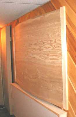 |
Photo courtesy of Avid Recorders. |
Real diffusor designs use an irregular surface having a complex pattern to scatter the sound waves even more thoroughly. Yet another type, shown below, uses chambers having different depths. Note that for diffusion to be effective, you need to treat more than just a few small areas. When walls are parallel, adding diffusion to only a small percentage of the surface area will not reduce objectionable echoes nearly as well as treating one or both walls more completely. Top
 |
Photo courtesy of RealTraps. |
Again, the angled and curved walls described earlier are deflectors, not diffusors. A true diffusor scatters sound waves in different directions based on their frequency, rather than merely redirecting all waves in the same direction. This is an important distinction because a flat surface that is angled or curved still fosters the boxy sounding response peaks and dips known as comb filtering. A real diffusor avoids direct reflections altogether, and thus has a much more open, transparent, and natural sound than a simple flat or curved surface. Besides sounding less colored than an angled or curved wall in a control room, diffusors serve another useful purpose in recording rooms: they can reduce leakage between instruments being recorded at the same time. Where an angled wall simply deflects a sound - possibly toward a microphone meant to pick up another instrument - a diffusor scatters the sound over a much wider range. So whatever arrives at the wrong microphone is greatly reduced in level because only a small part of the original sound arrived there. The rest was scattered to other parts of the room.
Unfortunately the better commercial diffusors are not cheap. So what are some alternatives for the rest of us? Aside from the skyline type diffusors, which are sometimes made of plastic and sold for not too much money, you can make a wall either totally dead or partially dead. For someone with a very small budget, making the rear wall of a control room totally dead may be the only solution. At least that gets rid of flutter echoes between the front and rear wall, though at the expense of sounding stuffy and unnatural. But it's better than the hollow boxy sound you get from a plain flat reflective surface. Another option is to make the rear wall of a control room partially reflective and partially absorbent. You can do this by making the wall totally dead, and then covering it with thin vertical strips of wood to reflect some of the sound back into the room. If you vary the spacing from strip to strip a little, you'll reduce the coherence of the reflections a little which further improves the sound.
Fast repetitive echoes - also called flutter echoes - can color the sound in the room and cause an emphasis at frequencies whose wavelengths correspond to the distance between the walls, and between the floor and ceiling. Flutter echoes are often identified as a "boing" sound that has a specific pitch. If you clap your hands in a live room or an empty stairwell or tunnel, you can easily hear the tone. If the room is large, you'll probably notice more of a rapid echo rat-a-tat-tat effect - the "flutter." Smaller rooms resonate at higher frequencies, so there you are more likely to hear a specific tone that continues even after the original sound has stopped. This effect is called ringing. Besides the obvious ill effects caused by the echoes, ringing creates an unpleasant sonic signature that can permeate recordings made in that room and negatively affect the sound of everything played through loudspeakers in that room. Top
Note that echo, flutter echo, and ringing are intimately related, so the delay time and pitch always depends on the distances between opposing surfaces. With small spacings the flutter echo's pitch is directly related to the distance. I have a long stairwell in my home with a spacing of 36.5 inches between walls. When I clap my hands loudly I hear a distinct tone at the F# whose pitch is about 186 Hz, and the half wavelength for 186 Hz is 36.5 inches. But with larger distances you may hear a higher frequency than the spacing would indicate, depending on what sound source excites the echoes. For example, when you clap your hands or otherwise excite a room with only midrange frequencies, the only resonances that can respond are also at mid/high frequencies. So if the distance between parallel walls fosters a resonance at, say, 50 Hz, you might hear 200 Hz, or 350 Hz, when you clap your hands.
Like diffusion, midrange and high frequency absorption helps minimize echoes and ringing. But unlike diffusion, absorption also reduces a room's reverb time. This makes the sound clearer and lets you hear better what is in the recording by minimizing the room's contribution. For example, if you make mixing decisions in a room that is too reverberant, you will probably add too little reverb electronically because what you hear includes the room's inherent reverb. Likewise, if the room is overly bright sounding due to insufficient absorption, your mixes will tend to sound muffled when played on other systems because the treble adjustments you make will be incorrect. Therefore, diffusion is used to avoid flutter echo, ringing, and comb filtering, but without reducing the room's natural ambience.
Low frequency absorbers - bass traps - can be used to reduce the low frequency reverb time in a large space, but they are more commonly used in recording studios and listening rooms to reduce modal ringing and flatten the frequency response in the bass range. This is especially true in smaller rooms where a poor low frequency response is the main problem. In fact, small rooms don't really have reverb at all at low frequencies. Rather, ringing at the room's individual mode frequencies dominates. But in large recording studios, churches, and auditoriums, reducing low frequency reverb is an important reason for adding bass traps. Top
MIDRANGE AND HIGH FREQUENCY ABSORBERS
Without question, the most effective absorber for midrange and high frequencies is rigid fiberglass. Owens-Corning 703 and 705, or equivalents from other manufacturers, are the standard absorbing materials used by professional studio designers. Besides being extremely absorbent they are also fireproof and, when applied to a wall, can even retard the spread of heat. Rigid fiberglass is available in panels 2 by 4 feet and in thicknesses ranging from 1 to 4 inches. Larger sizes are available, but 2 by 4 is more convenient for most studio applications, and can be shipped more economically. As with all absorbent materials, the thicker it is, the lower in frequency it will absorb to. That is, 703 fiberglass one inch thick absorbs reasonably well down to 500 Hz. When two inches thick, the same material is equally absorbent down to 250 Hz. See the sidebar Measuring Absorption for more information about how these measurements are made.
For a given thickness, 703 is about twice as absorbent as acoustic foam at the lower frequencies, and it generally costs much less. Even better for low frequencies is 705-FRK, which is much more absorbent than 703 at 125 Hz and below. FRK stands for Foil Reinforced Kraft paper. This is similar to the paper that grocery bags are made of, but with a thin layer of metal foil bonded to one side. The FRK paper was not intended for acoustic purposes, but to serve as a vapor barrier in homes. It just happens to be good acoustically too. Be aware that the paper reflects mid and high frequencies when installed with that side facing the room; this may or may not be desirable for a given application. 705 is also available without a paper backing. Top
Although 703 and 705 fiberglass panels are more effective than foam of the same thickness, they are usually covered with fabric for appearance, and to prevent the glass fibers from escaping into the air. This adds to the expense and difficulty of building and installing them. (In practice, fiberglass particles are not likely to escape into the air unless the material is disturbed.) A comparison of 703, 705-FRK with the reflective paper exposed, and typical foam is shown in Table 1 below. Note that foam panels sold as acoustic treatment are often sculpted for appearance, and to better absorb sound arriving at an angle. Removing some of the material reduces foam's effectiveness at low frequencies. If rigid fiberglass was compared to solid foam panels of the same thickness, the disparity in low frequency performance would likely be less. However, not having a sculpted surface would then reduce foam's absorption at higher frequencies.
|
||||||||||||||||||||||||||||||||
| Table 1: Absorption coefficients of 703, 705-FRK, and a popular brand of sculpted acoustic foam at different frequencies. All material is two inches thick and applied directly to a wall. This data was obtained from the respective manufacturer's published literature. |
It's not difficult to understand why 705 fiberglass is so much more absorbent than typical sculpted foam at low frequencies. Besides the fact that sculpted foam has about half the mass of solid foam due to material being removed to create the irregular surface, another consideration is density. According to test data published by several manufacturers of rigid fiberglass and rock wool, the denser types absorb more at low frequencies. The data published by Johns-Manville for their line of rigid fiberglass shown below is one example. Acoustic foam has a density of less than 2 pounds per cubic foot (pcf) [30 kg/m3] compared to 705 fiberglass which has a density of 6 pcf [90 kg/m3].
My own tests in a certified acoustics lab confirm this, showing denser types of rigid fiberglass absorb as much as 40 percent more than less dense types at 125 Hz and below. More recently I performed THIS series of measurements in my company's test lab, which shows the relationship between density and low frequency performance even more conclusively. Regardless of the reason, there is no disputing that for a given panel size and thickness, 705-FRK is substantially more effective at low frequencies than the same thickness of typical acoustic foam. However, it is important to understand that a material's density is but one contributor to its effectiveness as an absorber. Obviously, if the density is made too high the material will reflect more than it absorbs, so it's a mistake to conclude that higher densities are always better. For this reason, test data must be the final arbiter of a product's effectiveness. Top
 |
| As the data above clearly shows, 6 pcf rigid fiberglass panels absorb substantially more at low frequencies than less dense 3 pcf material. |
One important way to improve the low frequency performance of any absorbent material - besides making it thicker - is to space it away from the wall or ceiling. For a given material thickness, increasing the depth of the air gap lowers the frequency range it absorbs. For example, 703 that is two inches thick and mounted directly against a wall has an absorption coefficient of 0.17 at 125 Hz. Spacing the same material 16 inches away from the wall increases that to 0.40 - a nearly three-fold improvement. Of course, few people are willing to give up that much space in their rooms! And even very thick (four inch) 705-FRK with a one-foot gap will not absorb the lowest frequencies as well as a purpose-built bass trap which is optimized for that purpose. Bass traps, absorption coefficients, and spacing of absorbent material will be described separately and in more detail later. Top
IS "RIGID FIBERGLASS" AN OXYMORON?
There is some confusion about the term "rigid fiberglass" because it is not really rigid like a piece of wood or hard plastic. Rather, the term rigid is used to differentiate products such as 703 from the fluffy fiberglass commonly used for home insulation. Rigid fiberglass is made of the same material as regular fiberglass, but it is woven and compressed to reduce its size and increase its density. Rigid fiberglass that is one inch thick contains about the same amount of raw material as 3 to 6 inches of regular fiberglass. The photo below shows a piece of 703 one inch thick folded slightly. As you can see, it is rigid enough that it doesn't flop over when not supported (right side of photo), but not so rigid that it can't be bent or squeezed.
 |
703 "rigid" fiberglass is not really very rigid. |
Now that you know what rigid fiberglass is, where the heck do you buy it? You probably won't find it at your local hardware store or lumber yard, but many insulation suppliers stock it or can order it. Start by looking in your telephone directory under Insulation and also Heating / Air Conditioning Suppliers. You can find the name of an Owens-Corning dealer near you by calling 800-GET-PINK (800-438-7465) or from the Locator page on the Owens-Corning web site. Other companies, such as Knauf, Armstrong, and Delta, make similar products, and they often cost less than fiberglass from Owens-Corning. You can contact them directly to find a distributor near you. In the interest of completeness, here are some other manufacturers that make similar products: Johns-Manville, CertainTeed, Roxul, Ottawa Fibre, and Fibrex. Top
When assessing rigid fiberglass, it is important to know its density so you can compare equivalent products. Owens-Corning 703 has a density of about three pounds per cubic foot (45 kilograms per cubic meter), and 705 is about six pounds per cubic foot (90 kilograms per cubic meter). Therefore, products from other companies that have a similar density will have similar absorption characteristics at the same frequencies. Note that some companies call their products mineral wool, mineral fiber, or rock wool, but acoustically they are equivalent to fiberglass.
Rigid fiberglass is great stuff, and you can cut it fairly easily with a razor knife, but it's not very pleasant to work with because the fibers can make your skin itch. While handling it you should wear work gloves, and you won't be too cautious if you also wear a dust mask. The usual way to mount rigid fiberglass to a wall is with sheet rock screws and large diameter washers with a small hole, often called fender washers. These washers are needed to prevent the screw heads from pulling through the fiberglass. Fender washers are available at Home Depot and other hardware stores. If your wall is made of cement or brick, you can instead use construction glue like Liquid Nails to attach small strips of wood to the wall, and then screw the fiberglass to the strips. Since fiberglass works better when spaced away from a wall or ceiling, wood strips make sense even when you are able to screw directly into the wall. Top
Once the fiberglass is attached to the wall, you can build a wooden frame covered with fabric and place the frame over the fiberglass for appearance. If that's too much work, you can cut pieces of fabric and staple them to the edges of the wood strips. Nearly any porous fabric is appropriate, and one popular brand is Guilford type FR701. Unfortunately, it's very expensive. One key feature of FR701 is that it's made of polyester so it won't shrink or loosen with changes in humidity when stretched on a frame. But polyester is a common material available in many styles and patterns at any local fabric store. Another feature of FR701 is that it's one of the few commercial fabrics rated to be acoustically transparent. But since you're not using it as speaker grill cloth to place in front of a tweeter, that feature too is not necessary.
Shiny fabrics having a tight weave should be avoided because they reflect higher frequencies. The standard test for acoustic fabric is to hold it to your mouth and try to blow air through it. If you can blow through it easily, it will pass sound into the fiberglass. Burlap and Muslin are two inexpensive options, but nearly any soft fabric will work and also keep the glass fibers safely in place. Top
The most common application of bass traps in recording studios and control rooms is to minimize standing waves and acoustic interference which skew the room's low frequency response. (See the sidebar, Why They're Called Standing Waves.) As you can see in Figure 1 below, acoustic interference occurs inside a room when sound waves bounce off the floor, walls, and ceiling, and collide with each other and with waves still coming from the loudspeaker or other sound source. Left untreated, this creates severe peaks and dips in the frequency response that change as you move around in the room. At the listening position, there might be near-total cancellation centered at, say, 100 Hz, while in the back of the room, 100 Hz is boosted by 2 dB but 70 Hz is partially canceled. Top
 |
| Figure 1: Acoustic interference causes direct and reflected waves to combine in the air, creating peaks and dips in the frequency response. |
Here, a positive wave front from the loudspeaker (left) is reflected off the rear wall on the right, and the reflection collides with other waves that continue to emanate from the loudspeaker. Depending on the room dimensions and the wavelength (frequency) of the tones, the air pressure of the reflected waves either adds to or subtracts from the pressure of the waves still coming from the speaker. Worse, different locations in the room respond differently, with a boost at some frequencies and a reduction at others. When waves combine in phase and reinforce each other, the increase in level can be as much as 6 dB. But when they combine destructively, the dip in response can be much more severe. Level reductions of 25 dB or more are typical in untreated rooms, and near-total cancellation at some frequencies and locations is not uncommon. Further, most rooms have many peaks and dips throughout the entire bass range, not just at one or two frequencies. Figure 2 below shows the frequency response of the 10- by 16-foot untreated control room at a friend's studio. Note the large number of ripples, and their magnitude, all within just one octave! Top
 |
| Figure 2: Your worst nightmare? Yes, this response really is typical for an untreated small room! |
The action of sound waves colliding and combining in the air is called acoustic interference, and this occurs in all rooms at all low frequencies - not just those related to the room's dimensions. The only thing that changes with frequency is where in the room the peaks and nulls occur. The principle is identical to how phaser and flanger effects work, except the comb filtering happens acoustically in the air. Top
The only way to get rid of these peaks and dips is to avoid, or at least reduce, the reflections that cause them. This is done by applying treatment that absorbs low frequencies to the corners, walls, and other surfaces so the surfaces do not reflect the waves back into the room. A device that absorbs low frequencies is called a bass trap. Although it may seem counter-intuitive, adding bass traps to a room usually increases the amount of bass produced by loudspeakers and musical instruments. When the cancellations caused by reflections are reduced, the most noticeable effect is increasing the bass level and making the low frequency response more uniform. As with listening rooms, bass traps are also useful in studio recording rooms for the same reasons - to flatten the response of instruments captured by microphones and, with large studios, to improve the acoustics by reducing the low frequency reverb decay time which makes the music sound more clear.
For recording engineers, problems caused by standing waves and acoustic interference are often first noticed when you realize your mixes are not "portable," or do not "translate" well. That is, songs you have equalized and balanced to sound good in your control room do not sound the same in other rooms. Of course, variations from different loudspeakers are a factor too. But bass frequencies are the most difficult to judge when mixing because acoustic interference affects them more than higher frequencies. Another problem is that the level and tone quality of bass instruments vary as you walk around the room. The sound is thin here, too bassy over there, yet not accurate anywhere. Indeed, even if you own all the latest and most expensive recording gear, your mixes will still suffer if you can't hear what's really happening in the low end. Aside from portability concerns, it's very difficult to get the bass instrument and kick drum balance right when acoustic interference and modal ringing combine to reduce clarity. And when every location in the room has a different low-end response, there's no way to know how the music really sounds. Top
Many people wrongly believe that using near-field monitor speakers avoids the need for acoustic treatment. In truth, even with small loudspeakers playing softly, acoustic interference still causes standing waves - the imperfect frequency balance is exactly the same but at a lower level. Although higher frequency reflections and echoes are proportionately reduced as you get closer to the loudspeaker, the skewed frequency response caused by low frequency reflections remains. Likewise, adding a subwoofer will not fix problems that are due to poor room acoustics. While a subwoofer can be useful to compensate for inadequate loudspeakers, it will not solve the problem of an irregular response caused by acoustic interference. In fact, a subwoofer often makes matters worse by compounding and hiding the real problem.
Another common misconception is that equalization can be used to counter the effects of acoustic problems. But since every location in the room responds differently, no single EQ curve can give a flat response everywhere. Over a physical span of just a few inches the frequency response can vary significantly. Even if you aim to correct the response only where you sit, there's a bigger problem: It's impossible to counter very large cancellations. If acoustic interference causes a 25 dB dip at 60 Hz, adding that much boost with an equalizer to compensate will reduce the available volume (headroom) by the same amount. Such an extreme boost will increase low frequency distortion in the loudspeakers too. And at other room locations where 60 Hz is already too loud, applying EQ boost will make the problem much worse. Even if EQ could successfully raise a null, the large high-Q boost needed will create electrical ringing at that frequency. Likewise, EQ cut to reduce a peak will not reduce the peak's acoustic ringing. EQ cannot always help at higher frequencies either. If a room has ringing tones that continue after the sound source stops, EQ might make the ringing a little softer but it will still be present. However, equalization can help a little to tame low frequency peaks (only) caused by natural room resonance, as opposed to peaks and nulls due to acoustic interference, if used in moderation. Top
Yet another common misconception is that small rooms cannot reproduce very low frequencies, so they're not worth treating at all. A popular (but incorrect) theory is that very low frequencies require a certain minimum room dimension to "develop," and so can never be present at all in smaller rooms. The truth is that any room can reproduce very low frequencies, as long as the reflections that cause acoustic cancellations are avoided. When you add bass trapping, you are making the walls less reflective at low frequencies, so sound that hits a wall or ceiling will be absorbed instead of reflected. The net result is exactly the same as if the wall was not there at all - or as if the wall was very far away - whatever does come back is greatly attenuated due to distance and, therefore, not loud enough to cause as much cancellation. See the sidebar Big Waves, Small Rooms for more elaboration on this topic.
Some people mix using headphones in an attempt to avoid the effects of their room. The problem with headphones is that everything sounds too clear and present, making it difficult to find the ideal volume for some tracks. When listening through headphones, a lead vocal or solo instrument can be heard very clearly, even if it is quiet, so you'll tend to make it lower in the mix than it should be. Likewise, it's difficult to assess the amount of reverb and echo being added electronically when using headphones.
Note that standing waves and acoustic interference also occur at higher frequencies, such as sustained clarinet or flute tones. You can hear the effect and identify the problem frequencies and locations fairly easily by playing sine waves (not too loudly!) through your loudspeakers. This is also a good way to assess how important bass traps are for your particular studio and control rooms. If you have SoundForge, WaveLab, or a similar audio editor program, it's simple to create sine wave files at different low frequencies for testing. Special CDs that contain various tones and pink noise suitable for room testing and analysis are also commonly available. To determine the severity of low frequency problems, play different sine waves one at a time through your monitors, and then slowly walk around the room. It will be very obvious at which frequencies the peaks and valleys occur, and where they cause the most harm. There's no point in playing frequencies below what your speakers can produce cleanly - I suggest 60 Hz, 80 Hz, 100 Hz, and so forth through maybe 200-300 Hz. If you have a computer connected to your loudspeakers, you can download the NTI Minirator program. Top
Besides helping to flatten the low frequency response, bass traps serve another purpose that is equally important: They reduce the modal ringing that causes some bass notes to sustain longer than others, which harms clarity. The ETF 3D "waterfall" graph below shows the modal ringing in my 16'2" by 11'6" by 8' test lab. Both graphs show not only the low frequency response (the "back wall" of the graph), but also the bandwidth of each room mode and its decay time. As you can see, adding bass traps lowers the Q of modal peaks (widens their bandwidth) and also reduces their decay time. When the bandwidth of the modes is widened individual bass notes stick out less than other, adjacent notes. This solves the problem commonly known as "one note bass."
The other change is the large reduction in ringing time (the "mountains" come forward over time). Without traps, some bass notes ring out for as long as 1/3 of a second, so they muddy other subsequent bass notes. After adding bass traps the ringing time is cut in half or even less, except at the lowest mode which in this room is about 35 Hz. But even at 35 Hz there's a noticeable, if slight, improvement in bandwidth and decay time.
 |
| This ETF graph shows how bass traps reduce ringing by making it decay faster and lowering the Q of the resonances. |
Generally speaking, most rooms need as many bass traps as you can fit and afford. Although it is definitely possible to make a room too dead at midrange and high frequencies, you probably cannot have too much low frequency absorption. The effectiveness of bass traps is directly related to how much of the room's total surface area you treat, which includes the walls, floor, and ceiling. That is, covering thirty percent of the surface with bass traps reduces low frequency reflections far more than covering only five percent. It would be great to invent a magical acoustic vacuum cleaner that could suck the waves out from the air. But, alas, the laws of physics do not work that way. At the minimum I recommend placing bass traps in all of the corners. For even better results, put additional traps on the walls and optionally on the ceiling.
There are a number of ways to create a bass trap. The simplest and least expensive is to install a large amount of thick rigid fiberglass, spacing it well away from the wall or ceiling. As noted earlier, 705-FRK that is four inches thick and spaced 16 inches away from the wall can be quite effective to frequencies below 125 Hz. But many rooms have severe problems far below 125 Hz and losing twenty inches all around the room for thick fiberglass and a large air space is unacceptable to most studio owners and audiophiles. Fortunately, more efficient bass trap designs are available that are much smaller. However, studios on a tight budget can apply rigid fiberglass in the room corners as shown in Figure 3a and lose only the small amount of space in the corners. Since bass builds up the most in the corners of a room, this is an ideal location for any bass trap. Top
 |
| Figure 3a: A thick piece of 705 mounted across a corner is effective to fairly low frequencies. |
Figure 3a shows the corner viewed from above, looking down from the ceiling. When the rigid fiberglass is mounted in a corner like this, the large air gap helps it absorb to fairly low frequencies. For this application 705-FRK is better than 703 because the goal is to absorb as effectively as possible at low frequencies. However, you can either absorb or deflect the higher frequencies by facing the paper backing one way or the other, to better control liveness in the room. Using 705 fiberglass that is two inches thick does a good job, but using four inches works even better. Note that two adjacent two-inch panels absorb the same as one piece four inches thick, so you can double them up if needed. However, if you are using the FRK type you should remove the paper from one of the pieces so only one outside surface has paper. Top
Besides the corners where two walls meet as in Figure 3a, it is equally effective to place fiberglass in the corners at the top of a wall where it joins the ceiling. With either type of corner, you can attach the fiberglass by screwing it to 1x2-inch wood strips that are glued or screwed to the wall as described previously. The 1x2 ends of these strips are shown as small black rectangles in Figure 3a above. One very nice feature of this simple trap design is that the air gap behind the fiberglass varies continuously, so at least some amount of fiberglass is spaced appropriately to cover a range of frequencies.
When mounting 705-FRK directly to a wall - not across a corner - you'll achieve more low frequency absorption if the paper covered side is facing into the room. However, that will reflect mid and high frequencies somewhat. One good solution is to alternate the panels so every other panel has the paper facing toward the room to avoid making the room too dead. Panels attached with the backing toward the wall should be mounted on thin (1/4-inch) strips of wood to leave a small gap so the backing is free to vibrate. For fiberglass across a corner as shown in Figure 3a, the backing should face into the room to absorb more at low frequencies.
For a typical unfinished basement ceiling you can take advantage of the gap between the support beams and the floor above by placing rigid fiberglass between the beams. Short nails or screws can support the fiberglass, making it easy to slide each piece of fiberglass into place. Then cover the fiberglass with fabric as shown below in Figure 3b. You can optionally pack the entire cavity with fluffy fiberglass one foot thick and you'll probably get similar results. Top
 |
| Figure 3b: 705 between support beams, covered with fabric. |
Treating a "dropped" grid ceiling is even easier: Simply lay fluffy fiberglass batts on top of the grid, above the ceiling tiles. The thicker the fiberglass, the better. One foot thick R38 is perfect for this if you have the space. If you don't want to bother covering the entire ceiling that way, at least put fiberglass batts around the perimeter to treat the important wall-ceiling corners. And since the fiberglass is not exposed to the room and doesn't show, you don't need to cover it with fabric.
Another great and inexpensive way to make a bass trap - if you have a lot of room - is to place bales of rolled up fluffy fiberglass in the room corners. These bales are not expensive, and they can be stacked to fill very large spaces. Better still, they are commonly available and you don't even have to unpack them! Just leave the bales rolled up in their original plastic wrappers, and stuff them in and near the room corners wherever they'll fit. Stack them all the way up to the ceiling for the most absorption.
While increasing the depth of the air gap does indeed lower the frequency range absorbed, for thinner panels it can also reduce the absorption at some higher bass frequencies. The maximum amount of absorption for a given frequency occurs when the air gap is 1/4 the wavelength for that frequency. Figure 4 below shows the velocity of a sound wave, which is greatest as it transitions through zero. When it reaches the top or bottom of the cycle, the velocity is minimum, but the pressure is maximum. Because the velocity is greatest 1/4 wavelength from a boundary, more energy is present to force the waves through the absorbent material.
 |
| Figure 4: As a sound wave travels toward a boundary, the pressure and velocity are reset at the boundary. Therefore the wave has a maximum velocity 1/4 wavelength from the wall. At half a wavelength the velocity is minimum. Then it rises again at 3/4 wavelength. This pattern repeats indefinitely. |
The reason an absorbent material like fiberglass works better when spaced away from a surface is that sound waves passing through it have a greater velocity there. As a wave approaches a boundary, such as a wall, the velocity is reduced, and when it finally hits the boundary, the velocity is zero. Imagine a cue ball as it approaches the side rail on a pool table. The ball could be travelling 100 miles per hour, but at the exact point where it hits the rail the ball is not moving at all. Without motion there's no energy to be absorbed.
Likewise, fiberglass placed exactly at a rigid boundary does nothing because the air particles are not moving there. And since there's no velocity, the fiberglass has very little effect. As fiberglass is spaced further from the wall, the air particles passing through it have greater velocity. They are slowed down as they pass through the fiberglass, which converts the sound energy into heat therefore absorbing some of the sound. Top
 |
| Figure 5: Absorbent material is most effective when mounted with an air gap equal to 1/4 the wavelength of a particular frequency. But a gap that is ideal for one frequency is not ideal for all of the higher frequencies. |
As you can see in Figure 5 above, borrowed from Alton Everest's Master Handbook of Acoustics, absorption for a given gap depth is maximum at 1/4 wavelength multiples - in this case starting at around 250 Hz. It then falls off at a higher frequency where the gap depth equals 1/2 wavelength. It rises again when the gap matches 3/4 of the length of the next higher frequency, and so forth. This irregular absorption is most severe with thin absorbing materials, and gradually diminishes as the material is made thicker. You can avoid the reduction in absorption either by using thicker rigid fiberglass, or by filling the entire gap with material instead of using only a thin piece spaced away from the wall or ceiling. When the entire depth is filled, material is available to absorb all of the frequencies whose 1/4 wavelengths fall within that depth. Top
Although I promised not to use any math, I promise that the following simple formula is the only exception. To determine the best gap depth for a given frequency, you first need to determine the equivalent wavelength:
Wave Length in Feet = 1130 / Frequency
Then simply divide the result by 4 to get the optimum depth. So for 100 Hz the wavelength is 1130/100 = 11.3 feet, and 1/4 of that is about 2.8 feet. The number 1130 is the approximate speed in feet per second of sound waves travelling through air at normal room temperature and humidity.
For a given thickness of absorbent material, the ideal air gap is equal to that thickness because it avoids a hole in the range of frequencies absorbed. For example, if you install fiberglass that is four inches thick with a four-inch gap, higher frequencies whose 1/4 wavelength falls within the four-inch material thickness are absorbed regardless of the gap. And for those frequencies whose 1/4 wavelength is between four and eight inches, the fiberglass is also at the proper distance from the wall or ceiling. This is shown below in Figure 6. Top
 |
| Figure 6: The higher frequencies (top) are absorbed well because their velocity peaks fall within the material thickness. The lower frequency at the bottom does not achieve as much velocity so it's absorbed less. |
In practice, you don't necessarily have to measure wavelengths and calculate air gaps, and the first few inches of space yield the most benefit. Most people are not willing to give up two or more feet all around the room anyway, so just make the gap as large as you can justify. If you can afford to fill the gap entirely with material, all the better. And even though the velocity is indeed highest at 1/4 wavelength, there's still plenty at 1/8th of the wavelength too. Note that the angle at which sound waves strike a fiberglass panel can make the panel and its air gap appear thicker than they really are. Further, low frequency waves that strike an absorbing panel at an angle may be absorbed less than when they strike it at 90 degrees, due to a "grazing" effect. The explanations in this section are a simplification and are correct only for a 90 degree angle of incidence, which is not always the case.
I should mention another popular type of absorber, the tube trap, which is available commercially and also as do-it-yourself plans on various web sites. Although these are often referred to as "bass traps," even the largest tube models are not very effective below about 100 Hz, and the smaller ones become ineffective much higher than that. Marketing hype aside, the real absorption mechanism in a tube trap is simply the rigid fiberglass inside. The reason a 20-inch tube trap works at all down to 100 Hz is that the tube's diameter serves to space some of the fiberglass away from the nearest boundary, which helps extend its absorption to a lower frequency. But a tube design is no more effective than using plain rigid fiberglass spaced similarly. Top
Yet another type of bass trap is the Helmholtz resonator. Unlike foam, fiberglass, and tubes fitted with fiberglass, a Helmholtz resonator can be designed to absorb very low frequencies. This type of trap works on the principle of a tuned cavity and is often very efficient over a narrow range of frequencies. Think of a glass soda bottle that resonates when you blow across its opening, and you have the general idea. Although a Helmholtz design can be very efficient, the downside is that it works over a fairly narrow range and needs to be rather large to absorb very low frequencies. The range can be widened by filling the cavity with fiberglass, or by creating several openings having different sizes. One common design uses a box filled with fiberglass with its front opening partially covered by a series of thin wood boards separated by air spaces. This is called a slat resonator. Another also uses a box filled with fiberglass but has a cover made of pegboard containing many small holes. Although there is no denying that a Helmholtz trap can be very effective, the fact that it works over a narrow range of frequencies limits its usefulness. While it can be sized to absorb the dominant resonant frequencies in a particular room, it cannot absorb all the other low frequencies. And broadband absorption is needed to prevent acoustic interference that skews the frequency response throughout the entire bass range. Top
One of my favorite types of bass trap is the membrane absorber, also called a panel trap because it's made with a wood front panel. One huge advantage of membrane traps is that they do not have to be very thick to absorb very low frequencies. Because the bass range spans about four octaves, most panel traps are designed to work over only part of the bass range. Therefore, you will need an equal mix of trap types, with one intended to absorb the lower bass frequencies and the other for the higher bass range. Besides absorbing low frequencies very well, the wood front on a panel trap is reflective at higher frequencies. So installing enough of them to treat a room properly for low frequency problems will not make the room too dead sounding at mid and high frequencies.
The photo below shows eight panel traps I built for my home studio. Besides the panels, which are painted white, there are also many 703 fiberglass absorbers covered with tan fabric. Not shown are four more panel traps in the rear corners, plus another four on the side walls farther back in the room. The photo shows both types of panel traps (low-bass and high-bass), with the thinner units absorbing the higher bass range. Since this is a fairly large room for a home studio (18 by 34 feet), many traps are needed to cover a significant amount of the room's surfaces. A smaller room would need fewer traps to cover the same percentage of surface area. Top
 |
This room has an even mix of low-bass and high-bass panel traps, and an equal number of fiberglass absorbers to handle the midrange and high frequencies. More bass traps are in the rear of the room. |
Figure 7 below shows a cut-away view of a typical wood panel membrane trap. When a wave within the effective range of frequencies reaches the front panel, the panel vibrates in sympathy. Since it takes energy to physically move the panel, that energy is absorbed rather than returned into the room. The fiberglass then damps the plywood panel so it doesn't continue to vibrate. Were the panel allowed to vibrate freely on its own, less energy would be needed to keep it moving, so it would absorb less. Further, a panel that continues to vibrate on its own after the source sound stops actually generates sound similar to reverb and the ringing effect described earlier, and obviously that is not desirable! Top
 |
| Figure 7: Sound striking the plywood front panel causes it to vibrate. The fiberglass then damps that vibration. |
Similar to an acoustic suspension loudspeaker, panel absorbers like this one are sealed air-tight, and the fiberglass converts the acoustic energy into heat. Note how the fiberglass is spaced away from the back panel, which is more effective than simply attaching it directly against the rear surface. The closer the fiberglass is to the plywood panel, the more effectively it damps the panel's vibration. But it is important that the fiberglass not touch the panel because that would restrict its movement. For a panel trap to absorb as efficiently as possible, the panel must be free to vibrate with no restriction other than the damping action of the nearby fiberglass. Top
There are a few reasons for sealing panel traps. If there's a place for air to escape - let's say at the seam between the front panel and the side of the box - then pressure from the diaphragm as it pushes into the box will send the waves out the leak rather than push them into the fiberglass. Another, more relevant, reason is that a leak will let the internal pressure escape, reflecting the waves back into the room instead of absorbing them. Think of a panel trap as equivalent to an open window. If you cut a hole in an outside wall and cover the hole with a piece of heavy cardboard, the cardboard will reflect mid and high frequencies but let lower frequencies pass through. Those frequencies end up on the outside of the wall and so are not reflected back into the room. A sealed membrane bass trap is similar in that sound passing through the panel goes into the box and does not come out. But the most important reason a panel trap must be sealed is because the air inside acts as a spring, and an air leak reduces that effect.
Although mounting fiberglass across the corner of a room is best for treating bass frequencies, panel traps work on a different principle where the gap does not help. So with panel traps it's better to put two in each corner, flat against the wall, because that provides twice the surface area of just one trap mounted across the corner. Bass traps built from porous materials like fiberglass and acoustic foam work by absorbing the sound waves as they pass through the material. This type of trap is called a velocity absorber because it is velocity (speed) that drives the sound wave into the absorbing material. A wood panel trap works on an opposite principle, wave pressure, and is considered a pressure absorber because the wave pressure is greatest at the room boundaries. You can think of a wood panel bass trap as being a "shock absorber" for sound waves. As a wave approaches a wall it has plenty of velocity (the speed of sound) but no pressure. And when it hits the wall there's no longer any velocity but now there's plenty of pressure. This is similar to driving a car into a tree. You can be going 60 miles per hour toward the tree - lots of velocity - and the instant you hit the tree there's no velocity but plenty of pressure! Top
AS GOOD AS IT GETS?
Okay, so how much improvement can you really expect after installing bass traps? Unless you cover nearly all of the wall and ceiling surfaces with material that is 100% absorbent at all problem frequencies - which is pretty much impossible - you will still have some deviation from a perfectly flat response. But even with a more practical amount of treatment, you can achieve far less severity in the ripples and also increase their bandwidth so the peaks and dips are broader, making them less damaging and less likely to affect single bass notes. You'll probably still have peaks and dips that you can measure and identify with sine wave tests, but the music will sound much better, and the bass levels will vary much less around the room. The difference in frequency response of a room with and without membrane panel bass traps is shown in Figure 8 below.
 |
| Figure 8: That's more like it! This response plot is for the same control room shown in Figure 2 but after treatment with wood panel bass traps. |
PART 2: ROOM DESIGN AND LAYOUT
One of the most important properties of a room is its modes, or natural resonant frequencies which are related to its length, width, and height. More often than not the room you use for a studio or home theater has already been built, so knowing the modes and other permanent properties of the room is academic at best. After all, what's the point in calculating the modes if you can't do anything about them? And since all listening rooms need treatment at all low frequencies, knowing the modes doesn't even help you determine what type of bass traps you need. Perhaps you are lucky enough to have the luxury of designing an audio room and controlling its size and shape before it is built. In that case you can make a meaningful difference in the room's acoustic qualities by carefully choosing proper dimensions. If not, there's still plenty you can do to make an existing room as good as it can be. Top
The size and shape of a room determines its natural resonances - often called room modes. Every rectangular room has three sets of primary modes, with one each for the length, width, and height. If you have an irregular room shape or angled walls, you can average the dimensions to get a rough idea of the mode frequencies. That is, if the length wall is angled, making the width 10 feet at one end and 12 feet at the other, you can use 11 as the average for the width dimension. Rooms with irregular shapes, such as an alcove, have more than three sets of modes and are more difficult to calculate.
Generally speaking, larger rooms are better acoustically than smaller rooms because the modes are spaced more closely, yielding an overall flatter response. Acoustics experts recommend a minimum volume of at least 2500 cubic feet for any room in which high quality music reproduction is intended. Figure 9 below shows the modes for just one dimension - let's say the length - of two different rooms. Here, the larger room (top) has a length of 28 feet, so the fundamental mode frequency, which occurs at half the wavelength, is 20 Hz. Subsequent modes, similar to harmonics of a note played by a musical instrument, occur at 20 Hz intervals. Even though this creates many little resonant peaks in the response, the peaks are close together, so the average response is fairly flat. And as one peak is falling, the adjacent peak is rising to help compensate and fill in the void. (Please note that Figures 9 and 10 are approximations as drawn in a graphics program, so the shapes of the peaks and dips are not truly accurate.) Top
 |
| Figure 9: In a large room (top), the resonant peaks caused by modes are closer together than those in a small room (bottom). The closer spacing yields an overall flatter response. |
Now consider the length modes for the smaller room, shown at the bottom of Figure 9. Here the first peak is at 60 Hz, which corresponds to a half wavelength of about 9-1/2 feet. Therefore, subsequent modes occur at 60 Hz intervals making the overall response less uniform because a wider range of frequencies is attenuated, and more deeply, between each set of peaks. Top
Another important factor in the design of studios and listening rooms is the ratio between the length, width, and height. The worst shape is a cube having all three dimensions the same. A cube has the fewest number of peaks, and therefore the greatest distance between peaks, because all three dimensions resonate at the same frequencies. In an ideal room, each dimension will contribute peaks at different frequencies, thus creating more peaks having a smaller distance between them. This is shown in Figure 10 below.
 |
| Figure 10: The modes for a room with ideal ratios (top) give a more even response overall than a room with poor ratios (bottom). When the room proportions are less than ideal, some of the natural resonances are spaced far apart while others are clustered very close together. |
Besides making the overall response less uniform, uneven mode spacing can make one note on a bass instrument louder than adjacent notes. This is much worse than having a gentler curve created from many in-between peaks that, even if not flat, affects a wider range of notes. The principle is similar to using EQ to boost midrange presence in a recording - a broad boost always sounds more natural than a narrow one. Narrow peaks tend to impart a nasal quality that sounds like a wah-wah pedal set to a fixed point near the middle of its range. Note that besides creating peaks in the frequency response, the modes also determine at which frequencies the room's natural reverb is most pronounced. It is better for a room's reverb to be even across the spectrum rather than comprise a few dominant frequencies, which colors the sound unnaturally. So for all of these reasons a room should have different and non-related dimensions for the length, width, and height. When all three dimensions are the same - the worst case - you get widely spaced resonant peaks at the fundamental frequency and its harmonics only. With different dimensions you have more peaks at more in-between frequencies, which taken together gives an overall flatter response. Top
There are a few "ideal" ratios of room height, width, and length that professional studio designers agree should be used if possible. Three of these ratios, developed by L.W. Sepmeyer, are shown in Table 2.
|
||||||||||||
| Table 2: The ideal room has a ratio of height, width, and length similar to one of these. |
There are other good ratios, but those shown above are the ones I see referenced most often. Note that when a room has a suspended tile ceiling the real height, as far as low frequencies are concerned, is to the solid surface above the tiles. Likewise, in a basement with exposed joists the true height is to the bottom of the floor above, not the bottom of the joists. Top
That said, I believe the importance of room modes is often overstated. You don't want the width to be the same as the depth or an even multiple such as 10 feet by 20 feet. But the modes just describe where the resonances will be worst. Regardless of the room's size and shape, standing waves and acoustic interference happen at all low frequencies. So you still need bass traps that handle the entire range, not just the frequencies determined by the room modes. As far as acoustic interference is concerned, the only thing that changes with different room dimensions is where in the room the peaks and dips at each low frequency occur.
There are many freeware and web-based room mode calculators, but all the ones I've seen just list a table of the modes, so you still have to plot them by hand on semi-log graph paper to get a sense of how close they are to each other. Here is a link to ModeCalc (only 57 KB to download), a room mode calculator I wrote that runs in DOS and Windows. It plots the first ten primary room modes graphically so you can see how the modes are distributed and how they relate to one another. The modes for each dimension are displayed in a different color, and when two or more modes occur near the same frequency, the duplicates are shown on a separate line so one does not obscure the other. The program is easy to use, and pressing F1 displays complete instructions and explains how to interpret the results. Since the instruction manual contains additional explanations about room modes, it is reprinted below in the sidebar Room Modes and ModeCalc. Top
Unless you plan to record and mix in mono only, the symmetry of your room and loudspeaker placement are very important. If both loudspeakers are not situated symmetrically in a room they will have a different frequency response, and your stereo imaging will not be balanced. In a room that is longer than it is wide, it's better to place the speakers near the shorter wall so they fire the long way into the room as shown on the left in Figure 11 below. This puts you farther from the rear wall where the low frequency peaks and nulls are most severe.
|
||
| Figure 11: Symmetry matters! In a typical stereo mixing room, the loudspeakers are spaced equally from the walls and corners, and form an equilateral triangle at the mix position. The arrangement shown on the left above is better than the one on the right because it's more symmetrical within the room. The layout on the right also suffers from a focusing effect caused by the wall-wall junction behind the listener. |
Besides positioning the loudspeakers symmetrically, you should also place your console and chair so your ears are the same distance from each speaker. Likewise, acoustic treatment - whether absorption or diffusion - should be applied equally on both sides. In many home studios it is not possible to create a completely symmetrical arrangement, but you should aim for as close to this ideal as possible. Especially in the critical front part of the room where the first reflections to reach your ears are those from the side walls, and from the floor and ceiling if they're not treated with absorbent material. What happens in the rear of the room is probably less important. Top
Although the sample rooms shown above in Figure 11 are rectangular, I prefer angled walls and an angled ceiling because that provides deflection which reduces flutter echoes and ringing. Some people argue that parallel walls are preferred because you can better predict the room modes, and then treat the inevitable flutter echoes with absorption. But as I explained earlier, simply knowing the modes is not always that valuable, and with angled walls you can make the average dimensions comply with the ideal ratios. Further, if a room has parallel walls that must be treated with absorptive material to avoid echoes and ringing, you may not be able to make the room as live as you'd like. See the sidebar Creating a Reflection Free Zone for more related information.
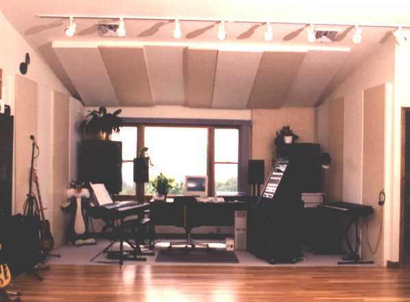
A peaked ceiling is better than a flat ceiling because it avoids the echoes and ringing that occur when the ceiling is parallel to the floor. But a peak creates a focusing effect, much like a parabolic dish, which is less than ideal. For this reason it's a good idea to place absorption or diffusion under the peaked portion, as shown in the photo below.
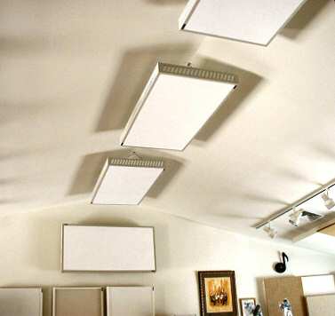 |
| These MiniTraps (commercial acoustic panels) were installed under the peaked ceiling in the author's home recording studio to avoid focusing sound in the room to the area under the peak. Top |
One somewhat controversial aspect of control room design is soffit mounting the main loudspeakers. Most home studio owners simply put their speakers on stands, or sit them on the mixing desk, and leave it at that. But many pro studios prefer to install the speakers into the wall so the front surface of the speaker cabinet is flush with the wall. There are sound scientific reasons to use soffit mounting, yet some engineers say it's not necessary or that it gives poorer results. Those in favor of soffit mounting point out that it reduces reflections called Speaker Boundary Interference, or SBIR, that cause peaks and dips in the low frequency response. If a loudspeaker is out in the room away from the wall, low frequencies from the rear of the cabinet will bounce off the wall behind it and eventually collide with the direct sound coming from the front of the speaker. (Even though it may not seem obvious, very low frequencies do in fact leave a speaker cabinet in all directions.) Proponents also claim that soffit mounting improves stereo imaging by reducing mid and high frequency reflections.
I happen to side with those in favor of soffit mounting, yet I also respect the opinions of those who disagree. One thing nobody will dispute is that soffit mounting requires a lot more effort! If you do use soffit mounting, please understand that the speakers must be built into the real wall. You can't just apply a lightweight facade around the front of the speaker cabinet and expect the same results. Top
LIVE OR DEAD - WHICH IS BEST AND WHERE?
If you've ever seen photos of high-end recording studios in magazines, you probably noticed that the studio room floors almost always use a reflective material like wood or linoleum. A hard floor gives a nice ambience when miking drums, guitar amps, and acoustic instruments. Likewise, auditorium stages and school band rooms always have a reflective floor surface too. As mentioned earlier, "live" in this context refers only to mid and high frequencies. I cannot emphasize enough the importance of a reflective floor for achieving a natural sound when recording acoustic instruments. If you record in your living room and your spouse refuses to let you remove the carpet, get a 4- by 8-foot sheet of 1/4-inch plywood to put over the carpet when recording. You can cut it in half for easier storage and put the halves next to each other on the floor when needed.
Control room floors are sometimes carpeted, sometimes wood, and often a combination of the two. Ceilings in these types of rooms also vary between fully reflective, fully absorptive, or a mix of surface types. There is no one correct way to treat every room because different engineers prefer a different amount of liveness. However, you should never make a room completely dead because that produces a creepy and unnatural sound. The only time you might consider making a room entirely dead is when treating a small vocal booth or a very small studio or control room - smaller than, say, ten by ten feet. When a room is very small the reflections are too short to be useful and just make the room boxy sounding. In that case the best solution is to cover all of the surfaces entirely with absorbent material and, for a studio room, add any ambience electronically later. Top
In a more typical room I recommend a mix of hard and soft surfaces for the walls, with no one large area all hard or all soft. I suggest applying absorbent material to the walls using stripes or a checkerboard pattern to alternate between hard and soft surfaces every two feet or so. This makes the room uniformly neutral everywhere. You can make the spacing between absorbent stripes or squares larger or smaller to control the overall amount of liveness. If you are using 705-FRK rigid fiberglass or an equivalent product, you can cover more of the wall and still control the liveness by alternating the direction of the paper backing. That is, one piece of fiberglass will have the paper facing the wall to expose the more absorbent fiberglass, and the next piece will have the paper facing out to reflect the mid and high frequencies. In fact, when the paper is facing into the room the lower frequencies are absorbed even better than when it is faces the wall.
Alternating hard and soft surfaces is also advisable with wood panel bass traps - simply place a fiberglass absorber between each trap. You can see this arrangement in the photo of my studio (above Figure 7), where each type of bass trap alternates with the other type and with fiberglass panels. That is, first is a low-bass trap, then a fiberglass panel, then a high-bass trap, then fiberglass, then low-bass, and so forth. I'll also mention that wood panel bass traps can be mounted horizontally when book shelves and other obstacles prevent placing them vertically. Since the corner formed by a wall and the ceiling, or a wall and the floor, is just as valid as any other corner, mounting a panel trap sideways near the top or bottom of a wall is equally effective.
Of course, many studios do have large live areas, and there's nothing wrong with that! If the room is big enough to avoid short echoes between closely spaced walls, having an entire wall reflective can yield a very big sound. And even in smaller rooms a hard floor with one or more bare walls can be useful. My cello teacher, who is a total audio neophyte, blew me away with the quality of a recording she made in her small Manhattan apartment. She recorded while playing with her back against the corner, facing into the room, using an inexpensive stereo mike placed a few feet in front of her cello. The key to a realistic and present sound, especially for acoustic instruments, is capturing some amount of ambience - even when the reverberation of a large space is not appropriate. Top
Although it is often desirable to alternate hard and soft surfaces on the walls, I often recommend covering the entire ceiling with absorbent material, especially if the ceiling is low. Besides eliminating floor to ceiling flutter echoes, full absorption can make the ceiling appear acoustically to be much higher. Most home studio owners cringe at the thought of making their ceilings even lower than they already are, but it really can help the sound. If you cover the entire ceiling with 2- to 4-inch thick 705, suspended with strings or wires to leave an air gap, the room will sound as if the ceiling were much higher. There's no difference between reflections that are reduced by the greater distance of a high ceiling and reflections from a low ceiling that are reduced by absorption. Using thick, dense fiberglass extends the simulated increase in height to lower frequencies. Where thin fiberglass makes the ceiling appear higher at midrange and high frequencies, using thicker and denser fiberglass with an air gap raises the apparent height at lower frequencies as well.
Another advantage of full absorption on a low ceiling is that it avoids the comb filtering that occurs when miking drums and other instruments from above. Placing microphones high over a drum set or string section puts the mikes very close to the ceiling. If the ceiling is reflective, sound will arrive at the mikes via two paths - the direct sound from the instrument and the same sound after being reflected off the nearby ceiling. When the difference in distance is very small, let's say one foot, the reflections cause many peaks and dips in the response, which are very audible and can sound like a flanger effect. (When reflections cause a series of peaks and dips, the effect is often called comb filtering because the frequency response plot resembles a hair comb.) Again, reducing strong reflections from a nearby ceiling via total absorption is acoustically identical to having a ceiling that's infinitely high. Top
Reducing noise and sound leakage is beyond the scope of this article, but I will share a few tips studio owners may find useful. If your studio has forced air ventilation, be sure to place the microphones away from the vents while recording. If the vents have adjustable deflectors, set them to direct the air away from where you normally place your microphones. Better, allow the room to get to the desired temperature before you start recording so you can turn off the blower. You can turn it on again between takes if needed. Likewise, radiators often make creaking sounds due to expansion and contraction as they warm up and cool down, so use them before you start recording.
Another troublesome noise source in many studios is the fan noise from a computer. You can buy a low noise replacement power supply from PC Power and Cooling and other companies. Easier, buy a computer from one of the better manufacturers because they often have much less fan noise than the cheaper brands. My last three computers were Dells, and they have all been very quiet. The small premium you pay for a better brand is easily gained back by not replacing the power supply or having to build or buy a sound proof enclosure.
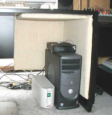
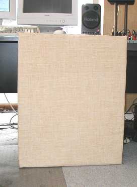
I also attached 703 fiberglass wrapped with fabric to the rear and underside of my desk, as shown in the photo below (left), to absorb the fan noise rather than reflect it into the room. Between the Dell's quiet power supply and the fiberglass, I can record myself playing the cello or acoustic guitar while sitting in front of the computer, with the mikes pointed right at me and the computer, and still pick up very little noise. A second piece of 703 (right) can be placed in front of the computer to reduce the noise even further while recording. Top
|
||
One easy way to reduce noise from a computer is to line the surrounding surfaces with absorbent material. |
If you've done all you can to reduce ambient noise and it's still too loud in a recording, consider using digital noise reduction. Many programs are available that do a remarkable job of removing any type of steady noise - not just hiss, but hum and air conditioning rumble too - after the fact. I use Sonic Foundry's Noise Reduction plug-in, but other affordable programs are available that also do an excellent job.
I have tried to make this article as complete as possible, but it's impossible to cover every aspect of acoustics. Many books have been written about acoustics and studio design, and my goal here is to cover only the issues that are most important to recording engineers and audiophiles. Further, acoustics is as much an art as a science, and surely mine are not the only valid opinions. Fortunately, the Internet offers many resources for more information including my own Audio Expert forum hosted by EQ Magazine, John Sayer's Studio Design forum, the Acoustics newsgroup, and Angelo Campanella's Acoustics FAQ. Perhaps the most valuable resource of all is Google, where you can find web pages that cover nearly any topic. Top
SIDEBAR: WHY THEY'RE CALLED STANDING WAVES
If you've ever used an ultrasonic cleaner to clean jewelry or small electronic components, you've probably seen standing waves in action. When you drop a pebble into a pond, a series of waves is created that extends outward from the point of impact. Since a pond is large, the waves dissipate before they can reach the shore and be reflected back to the place of origin. But in a contained area like the tub of an ultrasonic cleaner, the waves bounce off the surrounding walls and create a pressure front that makes them literally "stand still" within the cleaning solution. The exact same thing happens in your control room when your loudspeakers play a sustained bass tone. Static nodes develop at different places in the room depending on the loudspeaker position, the room's dimensions, and the frequency of the tone. Top
SIDEBAR: FINE TUNING THE CONTROL ROOM
Some recording studios use 1/3 octave graphic equalizers to flatten the frequency response of their monitor speakers. These equalizers are inserted into the signal path between the mixer and power amplifiers, to counteract the inevitable bumps and dips in any loudspeaker/room combination. Adjusting the frequency response of a room with equalizers is called "tuning the room."
When a manufacturer publishes response curves for a speaker, the measurements were made in an anechoic chamber - a room that is completely absorbent at all but the lowest frequencies. Eliminating reflections ensures that the measured response is accurate and not skewed by room reflections. But like a car maker's inflated mileage claims, measuring a loudspeaker's response in an anechoic chamber does not reflect reality. What really matters is the frequency response in your room. Top
There are different philosophies about the best way to tune a control room, and no one method is correct. What you do - if you do anything at all - depends on your mindset, the size of your wallet, and perhaps the kind of music you produce. Many people are satisfied to adjust the tweeter level on their speakers if one is provided and accept the results. If the speakers are bi-amped, the relative level between low and high frequencies can be further adjusted with the controls on the electronic crossover. Acoustic treatment as described in this article goes a long way toward eliminating response-skewing reflections, and with a properly treated room, equalization may not be worth the effort and expense. Further, all loudspeakers have their own unique "sound," and it's not wrong to pick speakers that sound the way you like and simply leave it at that.
Another philosophy is to aim for a perfectly flat response at any cost. Once the speakers have been made as flat as possible by adjusting the built-in controls and crossover, equalizers are added to the monitor signal path. If, for example, a 3 dB dip is measured at 1 KHz, the equalizers are set to boost that frequency by 3 dB to compensate. In practice the left and right equalizers are usually adjusted independently, since each speaker and its location in the room may require a different correction. Top
My personal philosophy is to avoid room equalizers because they can introduce as many resonant peaks and valleys in the response as they remove. And as explained in the main text, room equalization that improves the response in one part of the room almost always makes it worse in other places. Years ago I added a small amount of EQ cut at 400 Hz to the monitor system of my home recording studio, to correct a measured boost at that frequency. But after a year or so I removed the EQ because it seemed to make my mixes worse. I have heard similar reports from other studio owners - after going to great effort and expense to equalize their loudspeakers to make them perfectly flat, the result was generally poor and their mixes sounded worse in other rooms instead of better. But if you want to measure your own room just to know its response, following are a few ways to do that.
The old fashioned way to measure the frequency response of speakers in a room uses a pink noise signal source, a sweepable filter that passes 1/3 octave bands one at a time, a high-quality small-diaphragm omnidirectional condenser microphone, and a voltmeter with a decibel readout. All-in-one spectrum analyzers are available that combine these components into a single package, making the measurements fairly easy to perform. There are also software programs available that use your PC's sound card to play pink noise while recording from the microphone, and then display the room response. Top
Place the microphone at ear level where you sit while mixing. Then play the pink noise in mono through both of your loudspeakers, loudly enough to drown out all ambient noise by at least 30 dB. That is, the difference shown on the record level meter should be at least 30 dB between playing the noise and not playing the noise. Record about ten seconds of the noise from the mike onto a high quality medium like a DAT or a computer - 16 bits at 44.1 KHz is fine. Now load the file into SoundForge or another audio editor that offers a spectrum analyzer, and view the results at the highest resolution offered. You can also measure each speaker separately, if you'd like, or place the microphone in various locations in the room to measure the response in those places. The microphone does not have to be perfectly flat, as long as you know what its response really is and incorporate the deviation into your measurements. If you have an expensive mike, it probably came with a custom printed frequency response curve, and you can add/subtract that curve from your measurements to remove the mike's contribution to the results.
Another test uses plain sine waves, which more closely reflects real music, such as a bass player sustaining a note on a slow ballad. The sine wave test is similar to the test that uses pink noise, except you'll play a series of low frequencies one at a time and read the results on a meter. Start at the lowest frequency your loudspeakers are rated to reproduce, and continue at 1 Hz intervals up to about 300 Hz or so. I also suggest that you play a few individual tones and walk around the room listening for places where the tones get louder and softer. In most rooms if you play a single frequency, the difference between loud and soft will be 15 dB or more, and complete cancellations are common.
There are also more modern and sophisticated analysis tools such as TEF and the ETF and Smaart programs. These systems measure much more than just the raw frequency response. They also take into account the delay time and frequency content of the reflections, the room's reverb time at different frequencies, and they offer more sophisticated ways to view and interpret the results. I use the ETF program and find it most worthwhile, especially considering its very reasonable cost. Top
The standard way to specify the effectiveness of absorbent materials is with an absorption coefficient. This number ranges from zero to 1.0, with zero doing nothing and 1.0 being 100 percent absorbent. Since all materials absorb more at some frequencies than at others, the absorption coefficient values are also accompanied by a frequency. This frequency is really an average of all frequencies within the stated third-octave band.
Material that has an absorption coefficient of 0.5 at a given frequency absorbs half of the sound and either reflects or passes the rest. For example, 703 rigid fiberglass that is two inches thick has an absorption coefficient of 0.17 at 125 Hz. Because this frequency is at the low end of the fiberglass's useful range, the other 83 percent of the sound passes through it. On the other hand, 705-FRK fiberglass becomes more reflective at higher frequencies because of the metalized paper facing, so its absorption coefficient of 0.34 at 4 KHz means that the other 66 percent is reflected off the surface back into the room. Out-of-band frequencies for other materials are also either reflected or passed. A wood panel bass trap that absorbs well between 50 Hz and 200 Hz reflects most of the higher frequencies because of the hardness of the wood front panel, while lower frequencies instead pass through the trap to the wall behind. Top
Note that sound usually passes through absorbent material twice - once on its way toward the wall, and once again after being reflected off the wall back toward the room. Unless, of course, it's a very low frequency that first passes through the material, and then passes through the wall too. Even when a material like foam or fiberglass passes a low frequency instead of absorbing it, the wall will likely reflect the sound, so the net result is reflection.
Some vendors specify absorption using sabins instead of absorption coefficient, perhaps because it obscures the results and gives a larger number that is more impressive looking! After all, who wouldn't prefer a product that offers 9.0 sabins of absorption compared to one having an absorption coefficient of only 0.12? However, specifying absorption in sabins is sometimes justified, such as for tests of non-standard materials or when using unconventional mounting where the standard methods do not apply. You can convert sabins to an equivalent absorption coefficient by simply dividing the sabins by the square feet of front surface area.
Besides giving the absorption values at different frequencies, many product specifications also include the Noise Reduction Coefficient, or NRC. This is an average of just the midrange bands (250 Hz through 2.0 KHz) and is not useful when comparing materials for recording studios and music rooms. For example, one material may absorb mainly low frequencies while another works best at higher frequencies, yet both can have similar NRC values. Table 1 in the main text shows the NRC for 2-inch foam as 0.80 while the same thickness of 705-FRK is only 0.60. Yet 705-FRK is nearly six times more absorbent than foam at 125 Hz! Top
Absorption is typically measured in a special room that is very reverberant at all frequencies. The reverb decay time is measured at each frequency of interest with the room empty, and then again with the test material present. By comparing the difference in reverb times with the room empty and with the test material in place, the amount of absorption can be computed. Some minimum amount of material is required for testing so that the difference in decay times is large enough to ensure accurate measurements. In the tests I observed at IBM's acoustic labs, at least 64 square feet of material is required in order for the test results to be certified.
The standard way to measure reverb time is to play an impulse sound, such as a burst of pink noise through loudspeakers, and then measure how long it takes for the sound to fall by 60 dB. This type of test is called RT60, where RT stands for Reverb Time and 60 indicates the time it takes to fade by that many decibels. But it's difficult to measure levels that low because of ambient noise in the measuring room. So more often these tests measure the time it takes the reverb to decay by 30 or even 15 dB, and the time it would have taken to fall the full 60 dB is calculated from that.
At IBM's lab broadband pink noise bursts are played through loudspeakers, and a high quality microphone records each burst and its decay. A single test takes about 40 minutes to run because one hundred separate noise bursts are played. Since pink noise is random in nature the results of all the tests are averaged, separated into 1/3 octave bands. While the noise is playing the microphone that records the sound is constantly moving around the room. Instead of just placing a mike in one location, a special motorized boom stand rotates slowly in all three dimensions. That is, it swings around the room in a circle and also goes up and down from a few feet off the floor to seven or eight feet high. This way the reverberation at many places in the room is averaged into the measurements. Top
Another type of absorption test places the material being tested in a device called an impedance tube. This is a long narrow sealed chamber made of concrete or brick in which standing waves along the length of the tube are measured with and without the test material present. When using either test method, the ambient temperature and humidity must be constant and known precisely, as these affect the absorption of air and thus must be factored into the measurements.
Labs that perform acoustic tests are certified by NVLAP, a department of the US Government's National Institute of Standards and Technology. Testing of acoustic materials is defined by ASTM, a US organization that establishes standards and practices used by acousticians and their companies. By ensuring that its members follow exactly the same rules and guidelines, materials tested to ASTM standards in different facilities can be compared with confidence.
Most absorption measurements are taken with the test material mounted directly to a wall. But since spacing absorbent material away from a wall improves its low frequency performance, absorption figures that include spacing are often included in published specifications. In this case the specs indicate the type of mounting and also the spacing. The "A" mounting method means the material is flat against a wall, and E-### means the material was spaced, where the number (###) indicates the size of the air gap in millimeters. E-400 is common, which is about 16 inches. When "E" mounting measurements are made according to ASTM standards, a reflective skirt is applied around the edges of the material that extends to the mounting surface. This prevents reflections from bouncing off the mounting surface at an angle and entering the material from behind, which would wrongly increase the absorption measurements. Top
You may notice that absorption coefficients sometimes have a value greater than 1.0. Although it is impossible for any material to absorb more than 100 percent of the sound, measurements can yield a value greater than 1.0. The main reason this occurs is that all material has a finite thickness, and the edges - which are not included in the stated surface area - absorb some of the sound. So for a piece of 703 fiberglass that is two by four feet and four inches thick, the real surface area includes the four-inch thick edge around the material. If included in the measurements, this would add four square feet to the stated surface area of eight square feet - a 50 percent increase! (See the sidebar The Numbers Game for a more detailed explanation.) But even when the edges are included in the total surface area, values greater than 1.0 are still possible due to diffraction effects at the material's corners. When the corners are rounded, this effect is reduced.
As you might imagine, the fee to use a lab that performs certified acoustical testing is high because it's very expensive to build a reverberation test room. Such a room must have a very low ambient noise level, which requires isolated structures, special sound proof doors, and a low air flow ventilation system. Building a room large enough for testing very low frequencies is even more expensive. For this reason it is rare to see absorption specifications that extend below 100 Hz - it simply costs too much to build a room that can measure absorption accurately below that frequency. Further, most industrial manufacturers - the main customers of testing labs - do not need measurements at very low frequencies. However, even when a room is certified down to only 100 Hz, it is still possible to assess relative absorption. That is, you can test different materials at, say, 50 Hz and see which are more absorbent even if the absolute measurements are not guaranteed accurate. Top
Acoustic products are commonly specified by their absorption coefficient. This number ranges from zero (no absorption) to 1.0, meaning 100 percent of the sound is absorbed. For example, an absorption coefficient of 0.5 means that half the sound is absorbed and the other half either passes through the material or is reflected. Since no material absorbs all frequencies by the same amount, absorption coefficients are usually given for different frequency ranges.
Although 1.0 is the largest legitimate value possible, you may have seen higher numbers claimed for some products. Needless to say, this causes confusion, and makes it difficult to compare published data. Once you understanding how absorption is measured, and how data can be manipulated - both fairly and unfairly - you'll be able to assess room treatment products and materials more wisely.
Acoustic absorbers are tested using methods defined by the ASTM, a US organization that establishes standards and practices used by acousticians and testing labs. By requiring its members to follow the same rules, materials tested to ASTM standards in different facilities can be compared with confidence. However, a flaw in the test method does not take into account the edges of the material. Top
Although the edges are exposed when the material is tested, the calculation for absorption coefficient considers only the size of the front surface, and ignores the edges completely. For a panel that is two by four feet and four inches thick, the edges add 50 percent to the absorbing surface during testing, yet they are ignored in the coefficient calculation. This is further complicated because there is no standard sample size. Since a small sample has proportionally more edge than a larger one, a sample that's 8 by 8 feet will measure better than one that's 10 by 12 feet, even if they're the same thickness and made of the exact same material.
In practice, multiple panels are placed adjacent to each other during testing, to minimize the contribution of the edges. So when 2 by 4 foot panels are tested, typically eight of them are arranged into a larger square. But even when placed to form a single surface area of 8 by 8 feet, four-inch thick edges still inflate the measurements by more than 16 percent. Top
 |
| This panel is 2 by 4 feet and 4 inches thick. During testing the four edges add 50 percent to the total surface area, yet they're excluded from the absorption calculations. And when many panels are mounted adjacent on a wall, the edges are not absorbing even though they contributed to the published specs. |
Further, most acoustic panels are meant to be installed adjacent on the wall in a cluster. In this case the edges are not available to absorb even though they were when the material was tested. When an entire wall is covered with four-inch thick panels none of the edges are exposed, so the real absorption is only 2/3 what the published numbers indicate - and those numbers were already inflated!
The same thing occurs with corner absorbers, as shown in the figure below. Unless the vendor describes how these triangle shaped samples were grouped during testing, there is no way to determine how much of the stated absorption is due to the edge effect and how much is due to its effectiveness as an absorber. Top
 |
| Foam blocks like this are meant to be mounted in a corner, stacked one above the other from floor to ceiling. When measured for absorption four of the five surfaces are exposed, but when installed as intended only the front surface absorbs. So in practice, a two-foot corner wedge like this provides only 65 percent of the absorption claimed. The shorter the wedge, the larger the disparity between the published and actual absorption. |
For some products, like a tube trap, it is not practical to specify an absorption coefficient because there is no front surface. In that case the correct way to specify absorption is in sabins, named for acoustics pioneer W.C. Sabine (1868-1919). The sabin is an absolute measure of absorption, independent of surface area, and it can be used to compare any two absorbing devices directly and on equal terms. Top
SIDEBAR: BIG WAVES, SMALL ROOMS
There is a common myth that small rooms cannot reproduce low frequencies because they are not large enough for the waves to "develop" properly. While it is true that low frequencies have very long wavelengths - for example, a 30 Hz wave is nearly 38 feet long - there is no physical reason such long waves cannot exist within a room that is much smaller than that. What defines the dimensions of a room are the wall spacing and floor-to-ceiling height. Sound waves generated within a room either pass through the room boundaries, bounce off them, or are absorbed. In fact, all three of these often apply. That is, when a sound wave strikes a wall some of its energy may be reflected, some may be absorbed, and some may pass through to the outside.
When low frequencies are attenuated in a room, the cause is always canceling reflections. All that is needed to allow low frequency waves to sound properly and with a uniform frequency response is to remove or at least reduce the reflections. A popular argument is that low frequencies need the presence of a room mode that's low enough to "support" a given frequency. However, modes are not necessary for a wave to exist. As proof, any low frequency can be produced outdoors - and of course there are no room modes outdoors! Top
Here's a good way to look at the issue: Imagine you set up a high quality loudspeaker outdoors, play some low frequency tones, and then measure the frequency response five feet in front of the speaker. In this case the measured frequency response outdoors will be exactly as flat as the loudspeaker. Now wall in a small area, say 10x10x10 feet, using very thin paper, and measure the response again. The low frequencies are still present in this "room" because the thin paper is transparent at low frequencies and they pass right through. Now, make the walls progressively heavier using thick paper, then thin wood, then thicker wood, then sheet rock, and finally brick or cement. With each increase in wall density, reflections will cause cancellations within the room at ever-lower frequencies as the walls become massive enough to reflect the waves.
Therefore, it is reflections that cause acoustic interference, standing waves, and resonances, and those are what reduce the level of low frequencies that are produced in a room. When the reflections are reduced by applying bass traps, the frequency response within the room improves. And if all reflections were able to be removed, the response would be exactly as flat as if the walls did not exist at all. Top
SIDEBAR: HARD FLOOR, SOFT CEILING
The following is from an exchange that took place in the rec.audio.pro newsgroup in May, 2003:
Bill Ruys asked: Why it is recommended to have bare (un-carpeted) floors in the studio? One web site I visited mentioned that a bare floor was a prerequisite for the room design with diffusors and absorbers on the ceiling, but didn't say why. I'm trying to understand the principal, rather than following blindly.
Paul Stamler: Carpet typically absorbs high frequencies and some midrange, but does nothing for bass and lower midrange. Using carpet as an acoustic treatment, in most rooms, results in a room that is dull and boomy. Most of the time you need a thicker absorber such as 4-inch or, better, 6-inch fiberglass, or acoustic tile, and you can't walk around on either of those. Hence the general recommendation that you avoid carpet on the floor and use broadband absorbers elsewhere.
Lee Liebner: the human ear is accustomed to determining spatial references from reflections off of side walls and floor, and a low ceiling would only confuse the brain with more early reflections it doesn't need. Everywhere you go, the floor is always the same distance away from you, so it's a reference that your brain can always relate to. Top
John Noll: Reasons for having wood floors: they look good, equipment can be rolled easily, spills can be cleaned up easily, provide a bright sound if needed, sound can be deadened with area rugs.
Ethan Winer: In a studio room, versus a control room, a reflective floor is a great way to get a nice sense of ambience when recording acoustic instruments. Notice I said reflective, not wood, since linoleum and other materials are less expensive than wood yet sound the same. When you record an acoustic guitar or clarinet or whatever, slight reflections off the floor give the illusion of "being right there in the room" on the recording. It's more difficult to use a ceiling for ambience - especially in a typical home studio with low ceilings - because the mikes are too close to the ceiling when miking from above. And that proximity creates comb filtering which can yield a hollow sound. So with a hard floor surface you can get ambience, and with full absorption on the ceiling you can put the mike above the instrument, very close to the ceiling, without getting comb filtering.
Dave Wallingford: I've always preferred wood floors for a few reasons: 1) It's easier to move stuff around, 2) You can always get area rugs if you need them, And the main reason: 3) Pianos sound like crap on carpet. Top
SIDEBAR: ROOM MODES AND MODECALC
Click HERE to download the Windows version of ModeCalc - our Graphical Room Mode Calculator (1.3 MB) that has a greatly improved interface and offers more information than the original DOS version below.There's nothing to install - just Unzip the files into any folder, then run the modecalc.exe program file.
If you have a slow dial-up connection you can click HERE to download the original DOS version of ModeCalc (only 56 KB).
ModeCalc runs on all Windows computers, and displays the axial modes for any rectangular room using dimensions you enter as either feet or meters. ModeCalc can help you design a new room that sounds as good as possible, or predict the low frequency behavior of an existing room. The tutorial below explains the basics of room modes, and tells how to use ModeCalc and interpret its results. Top
ModeCalc TutorialModeCalc calculates and displays the first 16 axial modes, up to 500 Hz, for any rectangular room using dimensions you enter as either feet and inches or meters. It can help you design a new room that sounds as good as possible, or predict the low frequency behavior of an existing room.
This tutorial explains the basics of room modes, and tells how to use ModeCalc and interpret its results. Please understand that ModeCalc is not meant to help you determine low frequency treatment for an existing room. Regardless of what is predicted (or measured using test equipment) the solution is always the same - as much broadband bass trapping as you can manage. Whether your current room happens to have favorable dimensions or not is irrelevant, unless you're willing to move the walls! Top
Room Modes
Room modes are natural resonances that occur in every enclosed space, and the frequency of each resonance is directly related to the room's dimensions. For example, a room 16 feet long has a mode at 35 Hz because walls that far apart provide a natural resonance at 35 Hz. Additional modes occur at multiples of 35 Hz because those frequencies also resonate in the same space. Wall spacing that accommodates one cycle of a 35 Hz wave also fits two cycles of 70 Hz, three cycles of 105 Hz, and so forth.
When you play a musical note having the same pitch as a natural resonance of the room, that note will sound louder and have a longer decay time than other notes. Of course, this is undesirable because some notes are emphasized more than others, and the longer decay times reduce clarity. Therefore, room modes are important because they directly affect the character of a room. Although room resonances can be reduced by adding bass traps, they cannot be eliminated entirely. Top
For this reason, rooms for recording and playing music are designed to have many resonances that are distributed evenly, rather than just a few resonances at the same or nearby frequencies. Playing music in a room with poor mode distribution is like listening through a 5-band graphic equalizer with one or two bands turned up all the way. A room with good modes is more like having a 31-band equalizer with all the bands turned up. The frequency response still isn't perfect, but all the small peaks combine to yield an overall response that's reasonably flat. Therefore, the frequency response of a room with many modes close together is flatter overall than a room that has fewer modes farther apart.
Small rooms have modes that are spaced farther apart than large rooms because the first mode in a small room starts at a higher frequency. For example, when the longest dimension of a room is only 10 feet, the modes for that dimension start at 56.5 Hz and are 56.5 Hz apart. In larger rooms the first mode is at a lower frequency so subsequent modes are closer together. Therefore, a large room has a flatter low frequency response because it has more modes spaced more closely. Top
The formula used by ModeCalc is extremely simple. For dimensions given in feet the first mode occurs at 1130 divided by twice the dimension. (1130 is the speed of sound in feet per second.) All subsequent modes are multiples of that result. When using meters the formula is 344 divided by twice the dimension. Twice the dimension is used because a room 10 feet long really has a total distance of 20 feet - the wave travels from one end to the other and back to complete one cycle. So for a room 10 feet long the first mode occurs at 56.5 Hz:
| 1130 | |
| = 56.5 | |
| 10 x 2 |
The second mode for that dimension is two times 56.5 or 113 Hz, the third is three times 56.5 or 169.5 Hz, and so forth to the tenth mode at 565 Hz. Top
Room Ratios
The worst type of room shape is a perfect cube - say, ten feet long, ten feet wide, and ten feet high - because all three dimensions are the same and all three dimensions resonate at the same frequency. A 10 foot cube shaped room will have a strong inherent resonance near 55 Hz, which is the open A string on a bass. So when that low A is played it will sound much louder than other notes. Such a room also has a longer natural decay time at that pitch, so A notes will sustain longer and conflict with other bass notes that follow.
A room whose dimensions are multiples of each other - for example, 10 feet by 20 feet - is nearly as bad because many of the same frequencies are emphasized. Therefore, the goal is to have a room shape that spreads the modes evenly throughout the low frequency range. This is done by designing the room with dimensions whose ratios of length, width, and height are as unrelated as possible. And here is where ModeCalc is useful because it tells you at what frequencies the modes occur and how close together they are. ModeCalc also shows you the ratios of the dimensions you entered, and lets you compare them to ratios commonly recommended by acoustic engineers and studio designers. Top
Using ModeCalc
Instructions at the bottom of the screen explain how to use the program. Simply enter the Length, Width, and Height using the Tab and Shift-Tab keys to go between fields, then hit Enter to see the result. Up to 16 modes for each room dimension are displayed graphically so you can see where they occur and how they relate to one another. Each set of modes is shown in a different color, and when two or more modes occur near the same frequency the mode lines are drawn taller. Note that the graphic display portion of ModeCalc uses logarithmic spacing. This is how octaves and musical intervals are arranged, and is also how mode spacing should be viewed.
You can also enter the room dimensions as meters and/or centimeters instead of feet by using m or M or cm or CM and so forth after the dimension values. Values can be entered with or without spaces, so '10m' and '10 m' both specify 10 meters. Likewise for feet and inches. Top
Many rooms are not rectangular, and in fact having angled walls or a vaulted ceiling is desirable. Unfortunately, with angles there is no direct way to determine the room modes exactly. Modes still exist - they're just more difficult to predict. If the angles are not too severe you can average the dimensions. For example, if the ceiling varies from 8 feet to 10 feet high, you can use 9 feet when entering the height.
When viewing the results look for an even spacing of the modes regardless of their color (good), and also look for multiple modes that occur at or near the same frequencies (bad). Also compare the ratios of the dimensions you entered with the recommended ratios, and compare your room's volume with the recommended minimum of approximately 2500 cubic feet or 70 cubic meters. Top
To make it easier for you to identify modes that are close together ModeCalc draws those mode lines taller, which simulates the larger response peak that occurs. The normal line height is marked with a thin gray horizontal line. When two modes are adjacent, or at least close, both lines are drawn taller. The closer the modes are to each other, the taller the lines appear. This also lets you identify modes that fall on identical frequencies. ModeCalc draws all the lines for one mode, then the next, and the next. So if several modes are at identical frequencies one line will hide the other. If you notice that an isolated line is higher than usual, that means there are at least two modes at that same frequency. You can then use the Frequency Table display to see them all. Also note that modes naturally become closer at higher frequencies. Therefore, having taller lines toward the right side of the graph is normal, and does not mean your room will really have that rising frequency response.
Finally, if you are using ModeCalc to check an existing room, please don't be discouraged by poor results. All rooms need bass trapping anyway, and poor modes can be improved enormously by adding a few more traps. You can also enter dimensions for a large room having one of the recommended ratios, such as 23.3 by 16 by 10 feet. Then you'll see how even with the recommended ratios the modes are still somewhat uneven, and two modes still sometimes occur at the same frequency. So unless you are willing to move the walls, just accept what you have, and maybe install a few more bass traps than you had planned for originally. Then relax and enjoy the music! Top
A Few Words About Mode Types
There are two basic types of room modes - axial and non-axial. Axial modes occur between two parallel surfaces, where non-axial modes take a more circuitous route travelling much like a cue ball going around a pool table in a diamond pattern. The two non-axial mode types are called Tangential (the reflected waves touch four room surfaces) and Oblique (the waves touch all six surfaces).
Every rectangular room has three axial modes, with one between the floor and ceiling, another between the left and right walls, and another between the front and rear walls. Axial modes are the most important type simply because they are the strongest. They contribute more to peaks and nulls, and modal ringing (extended decays), than non-axial modes. This is because the boundaries are parallel and so the distance between reflections is shorter too. Therefore, axial modes are the most damaging to accurate music reproduction, and the most important type to consider. Top
SIDEBAR: CREATING A REFLECTION FREE ZONE WHAT: A useful goal for any room where music plays through loudspeakers is to create a Reflection Free Zone (RFZ) at the listening position. The concept is very simple - to prevent "early reflections" from obscuring the stereo image. This occurs when sound from the loudspeakers arrives at your ears through two different paths - one direct and the other delayed after reflecting off a nearby wall. Just as damaging is when sound from the left loudspeaker bounces off the right wall and arrives at the right ear, and vice versa. Similarly, early reflections off the ceiling and floor can also harm clarity and imaging. In all cases the reflections obscures fine detail and make it difficult to localize the source of the sound or musical instrument. This drawing, viewed from above, shows the three main paths by which sound from a loudspeaker arrives at your ears. The direct sound is shown as black lines. The early reflections - a single bounce off a nearby surface - are the red lines, and late echoes and ambience arrive as shown in blue. In truth, the blue lines are much more complex and dense than the single path shown here, but this is sufficient to explain the concept. The general goal of a Reflection Free Zone is to eliminate the red early reflection paths by placing absorbing panels on the side walls in key locations. Not shown, but just as important to avoid, are early reflections off the ceiling, floor, and mixing desk if present. Top |
 |
WHY: When a direct sound is accompanied by an echo that arrives within 20 milliseconds or less, the ear is unable to distinguish the echo as a separate sound source. So instead of sounding like an echo or general room ambience, the sounds coming from different directions combine, which obscures clarity and confuses the stereo image. You can still tell when an instrument is panned all the way to the left or right, but the in-between positions are not as well defined. Put another way, listening to music in a Reflection Free Zone is similar to listening with headphones - musical instruments sound clearer, and their placement in the stereo field is much better defined.
) |
Click the image above to see a larger version. |
Another important reason to control early reflections with absorption is to reduce comb filtering. This is a very specific type of frequency response error that's caused when a source and its reflections combine in the air. Depending on the difference in arrival times, some frequencies are boosted and others are reduced. The graph at left shows the comb filter frequency response measured with and without MicroTraps at the first reflection points.
When the budget allows for dedicated construction, early reflections can be avoided by angling the side walls and sloping the ceiling upward. The studio below was designed by noted studio designer Wes Lachot, and offers a beautiful example of such construction. Given a large enough angle the reflections are directed behind the listening position without having to apply absorbing materials to the walls or ceiling. This lets you better control the overall ambience in the room because you don't need additional absorption just to get rid of the reflections. But most people do not have the luxury of building new walls, so the only option is to apply absorption at key locations. Top
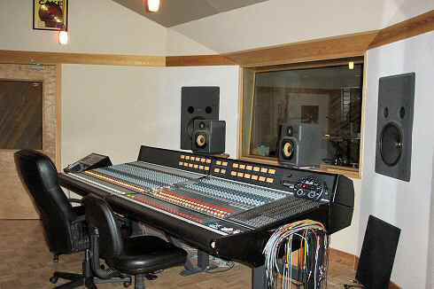
HOW: The easiest way to tell where to place absorption to avoid early reflections is with a mirror. This is the thin green object to the right of the listener against the wall in the drawing. While you sit in the listening position, have a friend place a mirror flat against the side walls and move it around. Any location in which you can see either loudspeaker in the mirror should be covered with absorption. It's a good idea to treat a larger area of the wall than you identify with the mirror, so you'll be free to move around a little without leaving the Reflection Free Zone. Once the side wall locations are identified do the same on the ceiling. Although it's more difficult to slide a mirror around on the ceiling, one way is to attach a hand mirror to a broomstick with rubber bands. Top
March 5, 2003: Initial release.
March 16, 2003: The paragraph just above Figure 5 was clarified by Wes Lachot. Thanks Wes!
March 20, 2003: Added Figure 3b and accompanying text showing how to install rigid fiberglass in an unfinished basement ceiling. Also added a new paragraph under Table 1 explaining the importance of density in absorbing materials.
March 22, 2003: Added a new last sentence to the second paragraph after Figure 7 offering a better reason panel bass traps must be sealed air tight.
March 25, 2003: Added the sidebar The Numbers Game to expand on the role of edges when testing absorbing materials.
March 28, 2003: Changed the formula for calculating the ideal 1/4 wavelength air gap (below Figure 5) from 1100 to 1130 feet per second, which is more accurate.
April 5, 2003: Added the sidebar Big Waves, Small Rooms to better debunk the myth that low frequencies require a minimum room size.
April 28, 2003: Added text (just below Figure 3b) describing using large bales of fluffy fiberglass as a bass trap.
May 14, 2003: Added the sidebar Hard Floor, Soft Ceiling to explain in more depth why that combination is better than a carpeted floor with a standard drywall ceiling.
June 10, 2003: Added a link to my Graphical Room Mode calculator program in the text below Table 2.
June 23, 2003: Added three sentences to the end of the paragraph under Figure 6 explaining how the angle of incidence can affect the absorption of a fiberglass panel. Thanks to Eric Desart for bringing this to my attention.
June 26, 2003: Added, clarified, and edited throughout to remove what some have perceived as my bias against foam treatment.
July 12, 2003: Added the online manual for ModeCalc (see June 10 above) as a sidebar, so you don't have to download and run the program just to read the explanation of modes.
August 28, 2003: Added the sidebar Creating a Reflection Free Zone above.
November 23, 2003: Added two paragraphs about diffusors in the section Diffusors and Absorbers, directly under the photo of the wood diffusor made by ACID acoustics.
January 14, 2004: Removed the qualification that the front wall angle must be "at least 35 degrees" in the RFZ sidebar because Wes Lachot says the exact minimum angle depends on several factors. Also made a few other minor edits to clarify the text.
April 21, 2004: Added a few more manufacturers of rigid fiberglass, and explained that FRK stands for Foil Reinforced Kraft paper.
April 26, 2004: Clarified the difference between a deflector and a true diffusor. Also, clarified the importance of density in porous absorber materials like rigid fiberglass.
May 4, 2004: Minor edits to the RFZ sidebar to make it clearer that early reflections from either side wall are a problem, not just the left wall with the right speaker and vice versa.
May 12, 2004: Added text under the Room Symmetry heading explaining the importance of having loudspeakers fire the long way into the room. It was a slow day so I also added several other minor enhancements and clarifications.
May 27, 2004: Replaced the graph I had made showing absorption versus air gap with a more compelling graph from Everest's Master Handbook of Acoustics. Also added test data from fiberglass manufacturer Johns-Manville showing how increasing the density of rigid fiberglass enhances its performance at low frequencies.
December 30, 2004: Enhanced ModeCalc to allow entering feet and inches (12'6") rather than having to use decimal feet (12.5).
February 11, 2005: Added a link to my Density Report in the section about fiberglass density. Added a new section under Bass Traps Overview to explain modal ringing. Added a paragraph to enhance the explanation of flutter echo.
February 21, 2005: Numerous minor edits, additions, and clarifications.
August 19, 2005: Added a paragraph to explain that two rigid fiberglass panels 2-inch thick can be combined to work as well as one panel 4 inches thick. Also added a warning not to have FRK paper between the layers, or on both the front and rear.
September 21, 2005: Clarified the difference between fiberglass bass traps that act on velocity versus wood panel traps that absorb via damping wave pressure.
February 3, 2006: Clarified that density is only one factor that affects a material's usefulness as an absorber, and that at some point the density can be too high.
March 9, 2006: Added text and a graph to the sidebar Creating an RFZ showing how comb filtering is an equally important problem that is solved by placing absorption at the first reflection points.
June 18, 2006: Added text near the end of the section Fiberglass Bass Traps explaining how to treat the cavity above a hung ceiling.
October 12, 2006: Updated the ModeCalc sidebar to link to the new Windows version, and updated the text to match.
August 10, 2007: Updated Figure 4 with an improved version submitted by Markus Mehlau.
December 2, 2008: Corrected and clarified Figure 4, its caption, and the surrounding text.
June 26, 2011: Added a link to the Hungarian translation by Bánfi Tamás.
July 2, 2014: Added the Bulgarian translation by Borislav Mihaylov.
![]() Ethan Winer is a reformed rock 'n'
roll guitarist who sold his successful software business in 1992 at the tender age of 43
to take up the cello. Ethan has, at various times, earned a living as a studio musician,
computer programmer, audio engineer, composer/arranger, technical writer, and college
instructor. He's had more than 200 feature articles published in audio, music, and
computer magazines including Mix, PC Magazine, EQ, Electronic Musician, audioXpress, and
many others. He's now a principal at RealTraps, manufacturer of high performance acoustic treatment, and
also hosts his own Audio
Expert Forum to answer questions about acoustics and anything else related to audio.
Ethan Winer is a reformed rock 'n'
roll guitarist who sold his successful software business in 1992 at the tender age of 43
to take up the cello. Ethan has, at various times, earned a living as a studio musician,
computer programmer, audio engineer, composer/arranger, technical writer, and college
instructor. He's had more than 200 feature articles published in audio, music, and
computer magazines including Mix, PC Magazine, EQ, Electronic Musician, audioXpress, and
many others. He's now a principal at RealTraps, manufacturer of high performance acoustic treatment, and
also hosts his own Audio
Expert Forum to answer questions about acoustics and anything else related to audio.
In addition to technical writing, Ethan has produced two popular Master Class videos featuring renowned cellist Bernard Greenhouse, as well as five CDs for Music Minus One including a recording of his own cello concerto. Besides writing and recording many pop tunes, Ethan has composed three pieces for full orchestra, all of which have been performed. He lives in New Milford, Connecticut, and has played in both the Danbury Symphony and the Danbury Community Orchestra where he served as principal cellist. Ethan's Cello Rondo music video has received nearly 2 million views on YouTube and other web sites, and his book The Audio Expert published by Focal Press, now in its second edition, is available at amazon.com and his Book web page. You can read more about Ethan's musical exploits on his Music and Articles pages. Top
Entire contents of this web site Copyright © 1997- by Ethan Winer and RealTraps, LLC. All rights reserved.